CAD Processor
This minor release includes enhancements in existing features, as well as numerous bugfixes.
CAD Processor SDK
CAD Processor SDK is now available as a standalone product for developers who wish to incorporate the algorithms of CAD Processor into their own software.
Sheet Metal improvements
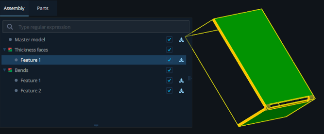
- Recognized sheet metal features can now be saved into a new model, where they will be represented as individual parts, grouped by feature type.
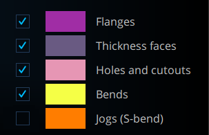
- Sheet metal features of different types can now be hidden or shown in the legend.
- Information on sheet metal parts (bends, operational folds, feature counts by type, etc.) can now be exported into CSV.
- The documentation now includes nomenclature of supported sheet metal features.
- Detection of crushed bends (hems) has been improved.
- Other improvements in sheet metal feature recognition.
Enhancements
- The command line version of CAD Processor for Linux no longer requires an X session to run and is therefore fully usable on headless servers.
- The Find Small Items tool can now search for items based on bounding box volume (in addition to diagonal).
- The Decimate Mesh tool now allows setting a minimum required number of polygons in meshes. Meshes smaller than this minimum will remain untouched.
- Detection of duplicated parts is now also supported for meshes.
- Commands Manager now has limitations on assignable hotkeys to ensure that keys already reserved for other things (e.g. Space, Ctrl+C) are not overridden.
- More intelligent selection mode behavior when switching between tools.
- Improvements in error reporting.
Fixes
- Fixed original assembly not showing in the model view after the Stitch Faces operation.
- Fixed part visibility being ignored in the model view after applying the Bound Parts operation.
- Fixed geometry corruption after repeatedly applying the Fill Gaps operation on some parts.
- Fixed blend chains being only partially recognized in some cases.
- Fixed some features being incorrectly recognized as blends in certain configurations.
- Fixed isolated feature detection failing to complete in some situations.
- Fixed Fill Gaps operation creating an empty B-Rep when applied to mesh parts.
- Fixed sub-shape colors being overridden by shape colors on model import.
- Fixed loss of color information when using Bound Parts on part compounds.
- Fixed application crash when undoing/redoing multiple operations in some cases.
- Fixed Composite ID changing on Linux after system reboot.
- Fixed dropping files onto CAD Processor window sometimes producing an error.
- Fixed sheet metal recognition never completing in rare cases.
- Fixed number of suppressed features being reported incorrectly.
- Fixed facet generation being impossible to undo.
- Fixed Polyhedrize Fibers operation failing in rare cases.
- Fixed blend suppression on thin-walled parts sometimes producing self-intersections.
- Other minor fixes.
This is the next major release of CAD Processor. The last several months of development resulted in a number of new tools and improvements.
First stage of Linux support
Fully functional version of CAD Processor CLI for Linux is now available. It will be distributed as an AppImage, allowing it to run on all modern distributions without any preparation.
Custom tools
CAD Processor is now more flexible than ever, thanks to the newly added ability to create custom tools by leveraging the power of scripting. You can write a script that operates on the model loaded into the desktop application, and then turn it into a GUI tool using the Commands Manager:
With special commands that allow retrieving/setting GUI selection from within scripts, custom tools can be made just as interactive as the stock tools of CAD Processor.
Fill by Extrusion
The new Fill by Extrusion tool allows quick defeaturing of part interiors by filling the space between two opposite faces. The extrusion is merged with any features intersecting it, completely removing the unwanted geometry:
Cap Holes
This tool is used for turning through holes into blind ones by capping them on one end. The «Select base faces» option allows capping only specific holes on a part, as well as controlling which end of the hole gets capped.
Hole capping can be useful on its own, or in combination with the Fill by Extrusion tool, when faces forming the part interior contain holes.
This tool comes with a «library» of detectable hole configurations that can be extended by adding new definitions in JSON format.
More tool improvements
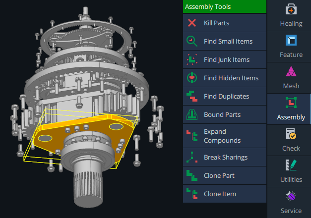
The Commands Manager mentioned above also allows rearranging the stock tools inside their respective menus, as well as hiding tools from the menus:
The Bound Parts tool has received a new mode, «Prism». In this mode, the part is replaced with a prism constructed on two opposite faces selected by the user.
It is now possible to dump selected faces or whole parts to JSON or B-Rep. This operation can be useful in scripts and custom tools, or to obtain new feature definitions for the Cap Holes tool.
Finally, the Wrap Geometry tool can now be tweaked using an optional configuration file.
Miscellaneous
- Extended information in the Parts list (facets, triangles) with the ability to sort by any column.
- Added an option not to visualize models automatically when loaded (helpful for very large assemblies).
- Added Undo/Redo history, with the ability to revert/restore multiple operations at once.
- The number of operations remembered for Undo/Redo is now configurable in the Settings.
- Detection of duplicates is now 5 to 20 times faster thanks to new optimizations.
- Added a context menu command to select all visible parts.
- Refined the backface coloring feature: now it also works on OBJ, glTF and other polygonal formats.
- Transitioned to OpenCascade 7.5.0.
- Models can now be exported to JT.
- Added multi-threaded building of triangulations for JT.
- Added a choice of shading model under Display settings.
- Most script commands now work in GUI even without an Enterprise license (except for loading and saving models).
- Tool menus/buttons are now locked during script execution.
- The COMPOSITE ID is now shown in the About menu even after activating the application.
- Expiration date is now shown for non-permanent licenses.
- Added the Default Radius parameter for Polyhedrize Fibers.
- Adjusted default values in Decimate Mesh.
- Added an item to the main menu that opens the User Manual.
- More polish for the User Manual.
- Some UI icons have been updated.
- Small improvements and fixes throughout the application.
This update perfects what has been achieved in the last major release of CAD Processor and adds a lot of quality of life improvements as well as some new useful tools.
Broader Format Support
A lot of formats have gained better support, and more data types can now be read from them. For instance, boundary representations inside JT are now supported. The formats that used to require additional licensing, such as CATIA or SolidWorks, are now available out of the box. glTF models can now be imported, and exporting to IGES has become possible.
Mesh Deviation Testing
This tool lets users visualize where the shape of a mesh deviates from a reference B-rep part and by how much. It works similarly to the Mesh Quality visualization and, just like the latter, provides another very intuitive way to inspect a model visually.
Maximize Faces
This new operation is useful when a user needs to get rid of multiple adjacent faces that all lie on the same surface, which makes them redundant. This tool effectively merges them, ensuring that every face is as large as it can be without distorting the model.
Extract Visible Triangles
This tools tests which triangles of a mesh can possibly be visible from the outside and discards the ones that are surrounded by other geometry and cannot be seen from any angle. As a result of this operation, the mesh loses a lot of its complexity and interior detail, which is useful for simplification and IP protection alike.
Upgraded Detection of Isolated Features
Detection of isolated features was available before, but only for features that completely lie on a single face (as in the first half of the animation below). Now it is possible to use the same tool to hunt down features that span multiple known faces.
Expanded Scripting
This update makes scripting even more powerful and versatile. CAD Processor team has implemented console commands for the few tools that lacked them and added some entirely new commands and helpers, for instance, a command to slice large objects into streamable fragments, a command to change the parent of an assembly item, and more.
Many existing commands have also been improved, their syntax reworked or extended to make them more straightforward and convenient to use. For example, whenever a user needs to pass a part to a command, he can define that part not only through its part ID, but also through the assembly item ID of any of its instances.
Scripting used to be available only in the Enterprise version of CAD Processor, but now the Desktop version also comes with the script editor which is built into the graphical user interface and can be used to develop scripts and execute them.
Finally, the built-in command reference has been updated with better command descriptions as well as some general formatting and readability improvements.
UI Makeover
Almost all user interface icons have been reworked, focusing on clarity, cohesion and a tidier, more aesthetic look. Many text strings and log messages are also revised to make them more concise and get rid of occasional misleading bits. Hopefully, this overhaul will make the software easier to get into and more pleasant to use.
Better Documentation
The user manual of CAD Processor has been almost completely re-written. Step-by-step directions for each task, completed with reworked animations and script examples where applicable, have been added. Several introductory sections have been added, specifically targeted at new users and CAD beginners. The document structure is greatly simplified: now most of it is no more than 2 levels deep, which makes it a lot easier to navigate and find desired topics.
Miscellaneous
There have been some more additions and improvements that deserve a brief mention.
- Added commands to clone parts and assembly items.
- Added the ability to convert a mesh to B-Rep faces.
- Added the ability to export individual parts to a file.
- It is now possible to load multiple files into the same scene.
- Added the ability to fuse parts geometrically.
- Added more details to the Model Contents panel.
- Added the Invert Selection action.
- CAD Processor CLI can now be passed a command or script at startup.
- Numerous performance and stability improvements throughout the program.
A number of new features and improvements was implemented for making the solution more powerful and richer in terms of functionality.
Detection and suppression of simple fillet chains
This feature allows for automatic detection and suppression of fillet chains while ensuring the topological consistency of the result. Based on our brand new implementation of Euler operators, the algorithm attempts to adjust the topology of a CAD model and then stitch the affected B-rep faces so that to end up with a watertight geometry. The company now has the first version of the algorithm, which guarantees that CAD models stay consistent upon completion of the operation. The efficiency of the computations behind (no expensive Booleans are employed) and its reliability make the new defeaturing algorithm especially suitable for batch simplification.

Enhancements in isolated features detector
Another defeaturing tool which is appreciated by our users is the detector of isolated features. With a couple of mouse clicks, this algorithm lets users erase various kinds of irrelevant details from your CAD model, starting from engravings and logos, and ending up with pockets and blind holes. In CAD Processor 1.0, one can now limit the size of the detected features, thus preventing the operation from being too disruptive.

Gap filling and repatching faces
Preparing CAD models for numerical simulation is another challenge that CAD Processor attacks. One of the needs which often arise is the generation of CAE meshes from the exact CAD data. As mesh generation gurus say, «Geometry modeling is to meshing what turbulence modeling is to computational fluid dynamics (CFD).» In particular, missing or narrow faces may lead the mesher to failure or to producing a non-applicable result in terms of quality. CAD Processor strives to release the simulation engineers from being stuck with that sort of problem. Two features from the «Healing» group may contribute to generating a better-quality mesh: gap-filling and repatching.
Enhancements in shrink wrapping
Open Cascade state-of-the-art shrink wrapping algorithm got dozens of improvements related to the general efficiency of computations and less critical, though still sweet things such as a more smooth progress indication. The shrink wrapping operation lets users generate watertight simulation-ready unstructured grids from dirty CAD parts and assemblies.

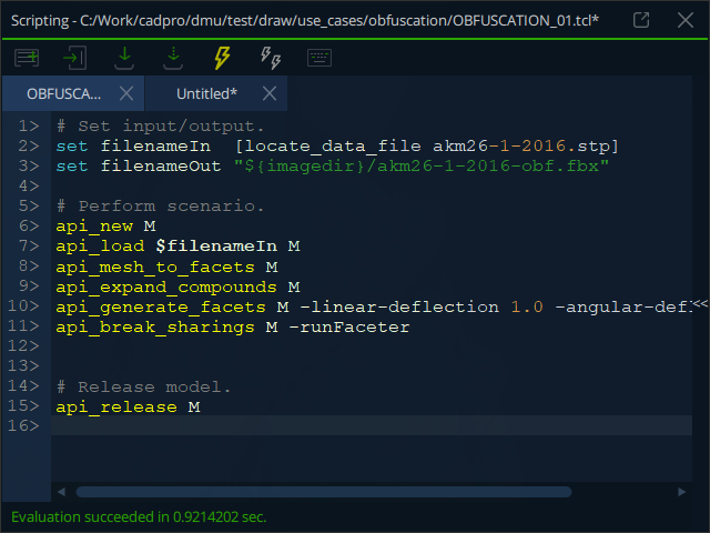
Obfuscation for IP protection
One of the new features available for the users of CAD Processor Enterprise is a visual obfuscation of the digital product’s shape. The new algorithm allows for generating lightweight mockups with distorted geometric dimensions. The obfuscated shapes are not operational for the downstream engineering workflows (i.e., simulation and manufacturing), and hence are perfect for IP protection.
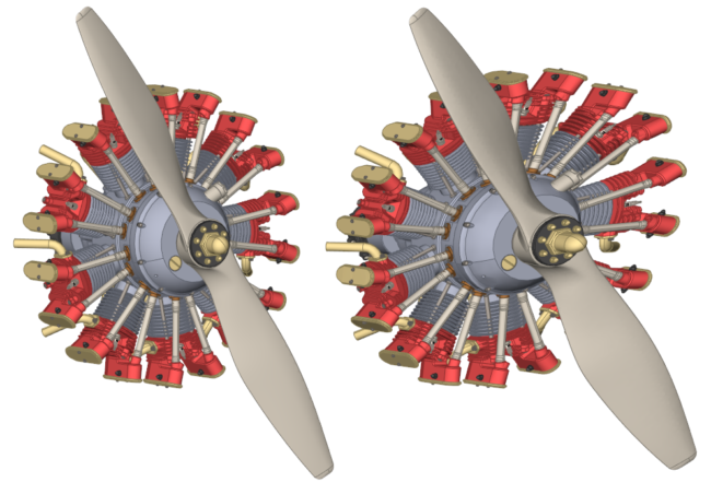 Sample assembly (courtesy of Dave Goetsch via GrabCAD) before and after obfuscation. The obfuscated model is a lightweight 3D object.
Some use cases for the obfuscation feature include generating shape previews for publishing in online catalogs and communicating the protected 3D models to your subcontractors.
Break sharing of assembly components
CAD Processor 1.0.0 got a function to grab a part/subassembly for local modification while not affecting its other occurrences. This feature is complimentary to our tool for the optimization of duplicated geometry. To appreciate the effect of this functionality, one should think of a CAD assembly as a hierarchical graph where each component’s occurrence is expressed as a directed link. Multiple links pointing from one assembly element to another mean that the corresponding part/subassembly is reused (with a different placement). While reusing a single prototype (the term we use to speak of the referenced parts/subassemblies) is a good thing itself, it may have some unexpected implications. E.g., defeaturing a single bolt instantiated ten times affects all ten instances of that bolt even if the user was supposed to touch a single object only. Now, users can break the sharing of a component and this way to isolate it for further modification by sacrificing a small amount of extra memory.
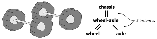 The hierarchical assembly graph composed of two part prototypes (wheel, axle), one subassembly prototype (wheel-axle), and five instances (graph arcs).
Detect bridges in sheet metal
One of the state-of-the-art algorithms available in CAD Processor is its feature-based sheet metal recognition and unfolding. The module allows for processing the conventional sheet metal parts: counting the holes, cutouts, bends; extracting the global sheet properties (perimeter, volume, surface); unfolding with the user-defined K-factor. In CAD Processor 1.0, the set of recognized features is extended with a new type: the bridges.

Fuse parts on combination
It is now possible to combine parts not only logically, but also geometrically. The new context-menu option «Convert to part with fuse» performs a Boolean set operation to generate a single-solid part from the input bodies. This new feature is useful for CAE engineers who are seeking a way to merge geometric domains prior to meshing.
Improve fibers polyhedrization
The algorithm of fibers polyhedrization is a unique feature of CAD Processor aimed at remeshing electricity harnesses to gain better visual quality. The algorithm substitutes the precise model of a tube, wire, or hose with its polygonal representation, ensuring having a regular polygon at a cross-section. Adjusting the coarseness parameters, users obtain different levels of detail, not compromising the spatial correctness of the final representation.
More CAD formats to import and export
CAD Processor can now read the vendor-specific proprietary data formats, such as CATIA V5/V6, NX, PTC, and others. The additional import tools are available as extensions to the basic functionality. Contact us to get more information.
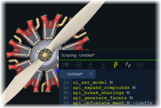
Embedded scripting panel
One of the most breakthrough features we now have in the CAD Processor Enterprise is the embedded scripting console. Users can use it for rapid prototyping, elaborating the simplification recipes and speeding up work on large models.
Enhanced visualization of meshes and metrics
The visualization module for meshes and mesh quality metrics was remastered to gain a better performance along with smoother appearance properties. Additionally, the current quality metric can now be selected right from the scalar bar. The scalar bar also got a supplementary histogram to show the distribution of mesh elements w.r.t. quality metric values.

Better oriented bounding volumes
The simplification feature consisting in the substitution of parts with their bounding volumes is improved to yield better-oriented shapes.

Usability improvements
Together with the key features outlined above, CAD Processor was slightly enhanced to improve the overall user experience. In particular, the following changes found their way to the Desktop and Enterprise versions of CAD Processor:
- The documentation can now be opened by pressing
key; - The faces with flipped orientation can now be easily tracked thanks to the enabled backface coloring (red color is used). If you’re not that concerned with the validity of your faces, you’re still free to turn off the backface coloring in the settings;
- A more responsive progress indication is now available;
- From now on, the clipping planes can be aligned not only with the main projection views but with any planar face selected by the user interactively;
- Rubber-band selection is now available. Use
key to activate it, and be aware that selection works differently depending on how you move the mouse pointer (from the top-left corner or from the bottom-right corner.)