|
Open CASCADE Technology
7.4.0
|
|
|
Open CASCADE Technology
7.4.0
|
|
This manual explains how to use the Open CASCADE Application Framework (OCAF). It provides basic documentation on using OCAF. For advanced information on OCAF and its applications, see our E-learning & Training offerings.
OCAF (the Open CASCADE Application Framework) is an easy-to-use platform for rapidly developing sophisticated domain-specific design applications. A typical application developed using OCAF deals with two or three-dimensional (2D or 3D) geometric modeling in trade-specific Computer Aided Design (CAD) systems, manufacturing or analysis applications, simulation applications or illustration tools.
Developing a design application requires addressing many technical aspects. In particular, given the functional specification of your application, you must at least:
Architectural guidance and ready-to-use solutions provided by OCAF offer you the following benefits:
OCAF is much more than just one toolkit among many in the CAS.CADE Object Libraries. Since it can handle any data and algorithms in these libraries – be it modeling algorithms, topology or geometry – OCAF is their logical supplement.
The table below contrasts the design of a modeling application using object libraries alone and using OCAF.
Table 1: Services provided by OCAF
| Development tasks | Comments | Without OCAF | With OCAF |
|---|---|---|---|
| Creation of geometry | Algorithm Calling the modeling libraries | To be created by the user | To be created by the user |
| Data organization | Including specific attributes and modeling process | To be created by the user | Simplified |
| Saving data in a file | Notion of document | To be created by the user | Provided |
| Document-view management | To be created by the user | Provided | |
| Application infrastructure | New, Open, Close, Save and Save As File menus | To be created by the user | Provided |
| Undo-Redo | Robust, multi-level | To be created by the user | Provided |
| Application-specific dialog boxes | To be created by the user | To be created by the user |
OCAF uses other modules of Open CASCADE Technology — the Shape is implemented with the geometry supported by the Modeling Data module and the viewer is the one provided with the Visualization module. Modeling functions can be implemented using the Modeling Algorithms module.
The relationship between OCAF and the Open CASCADE Technology (OCCT) Object Libraries can be seen in the image below.
In the image, the OCAF (Open CASCADE Application Framework) is shown with black rectangles and OCCT Object Libraries required by OCAF are shown with white rectangles.
The subsequent chapters of this document explain the concepts and show how to use the services of OCAF.
OCAF provides you with an object-oriented Application-Document-Attribute model consisting of C++ class libraries.
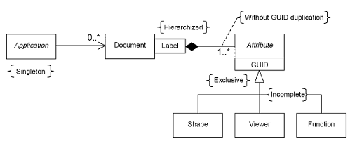
The Application is an abstract class in charge of handling documents during the working session, namely:
The document, implemented by the concrete class Document, is the container for the application data. Documents offer access to the data framework and serve the following purposes:
Each document is saved in a single flat ASCII file defined by its format and extension (a ready-to-use format is provided with OCAF).
Apart from their role as a container of application data, documents can refer to each other; Document A, for example, can refer to a specific label in Document B. This functionality is made possible by means of the reference key.
Application data is described by Attributes, which are instances of classes derived from the Attribute abstract class, organized according to the OCAF Data Framework.
The OCAF Data Framework references aggregations of attributes using persistent identifiers in a single hierarchy. A wide range of attributes come with OCAF, including:
In addition, application-specific data can be added by defining new attribute classes; naturally, this changes the standard file format. The only functions that have to be implemented are:
In most existing geometric modeling systems, the data are topology driven. They usually use a boundary representation (BRep), where geometric models are defined by a collection of faces, edges and vertices, to which application data are attached. Examples of data include:
When the geometric model is parameterized, that is, when you can change the value of parameters used to build the model (the radius of a blend, the thickness of a rib, etc.), the geometry is highly subject to change. In order to maintain the attachment of application data, the geometry must be distinguished from other data.
In OCAF, the data are reference-key driven. It is a uniform model in which reference-keys are the persistent identification of data. All accessible data, including the geometry, are implemented as attributes attached to reference-keys. The geometry becomes the value of the Shape attribute, just as a number is the value of the Integer and Real attributes and a string that of the Name attribute.
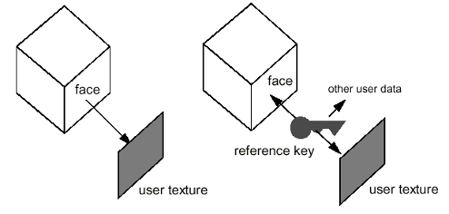
On a single reference-key, many attributes can be aggregated; the application can ask at runtime which attributes are available. For example, to associate a texture to a face in a geometric model, both the face and the texture are attached to the same reference-key.
Reference-keys can be created in two ways:
As an application developer, you generate reference-keys in order to give semantics to the data. For example, a function building a prism may create three reference-keys: one for the base of the prism, a second for the lateral faces and a third for the top face. This makes up a semantic built-in the application's prism feature. On the other hand, in a command allowing the end-user to set a texture to a face he/she selects, you must create a reference-key to the selected face if it has not previously been referenced in any feature (as in the case of one of the lateral faces of the prism).
When you create a reference-key to selected topological elements (faces, edges or vertices), OCAF attaches to the reference-key information defining the selected topology — the Naming attribute. For example, it may be the faces to which a selected edge is common to. This information, as well as information about the evolution of the topology at each modeling step (the modified, updated and deleted faces), is used by the naming algorithm to maintain the topology attached to the reference-key. As such, on a parametrized model, after modifying the value of a parameter, the reference-keys still address the appropriate faces, even if their geometry has changed. Consequently, you change the size of the cube shown in the figure above, the user texture stay attached to the right face.
Note As Topological naming is based on the reference-key and attributes such as Naming (selection information) and Shape (topology evolution information), OCAF is not coupled to the underlying modeling libraries. The only modeling services required by OCAF are the following:
Currently, OCAF uses the Open CASCADE Technology modeling libraries.
To design an OCAF-based data model, the application developer is encouraged to aggregate ready-to-use attributes instead of defining new attributes by inheriting from an abstract root class. There are two major advantages in using aggregation rather than inheritance:
Summary
The OCAF Data Framework is the Open CASCADE Technology realization of the reference-key model in a tree structure. It offers a single environment where data from different application components can be handled. This allows exchanging and modifying data simply, consistently, with a maximum level of information and stable semantics.
The building blocks of this approach are:
As it has been mentioned earlier, the first label in a framework is the root label of the tree. Each label has a tag expressed as an integer value, and a label is uniquely defined by an entry expressed as a list of tags from the root, 0:1:2:1, for example.
Each label can have a list of attributes, which contain data, and several attributes can be attached to a label. Each attribute is identified by a GUID, and although a label may have several attributes attached to it, it must not have more than one attribute of a single GUID.
The sub-labels of a label are called its children. Conversely, each label, which is not the root, has a father. Brother labels cannot share the same tag.
The most important property is that a label’s entry is its persistent address in the data framework.
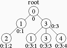
In this image the circles contain tags of the corresponding labels. The lists of tags are located under the circles. The root label always has a zero tag.
The children of a root label are middle-level labels with tags 1 and 3. These labels are brothers.
List of tags of the right-bottom label is "0:3:4": this label has tag 4, its father (with entry "0:3") has tag 3, father of father has tag 0 (the root label always has "0" entry).
Let's have a look at the example:
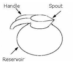
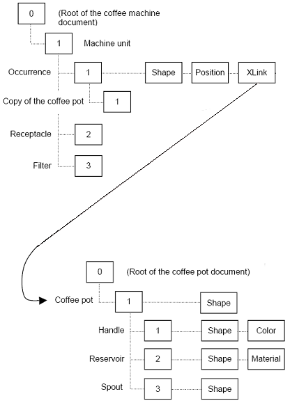
In the image the application for designing coffee machines first allocates a label for the machine unit. It then adds sub-labels for the main features (glass coffee pot, water receptacle and filter) which it refines as needed (handle and reservoir of the coffee pot and spout of the reservoir).
You now attach technical data describing the handle — its geometry and color — and the reservoir — its geometry and material. Later on, you can modify the handle's geometry without changing its color — both remain attached to the same label.
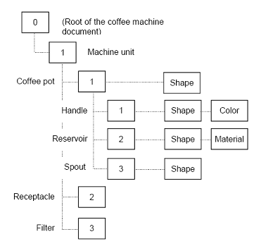
The nesting of labels is key to OCAF. This allows a label to have its own structure with its local addressing scheme which can be reused in a more complex structure. Take, for example, the coffee machine. Given that the coffee pot's handle has a label of tag [1], the entry for the handle in the context of the coffee pot only (without the machine unit) is [0:1:1]. If you now model a coffee machine with two coffee pots, one at the label [1], the second at the label [4] in the machine unit, the handle of the first pot would have the entry [0:1:1:1] whereas the handle of the second pot would be [0:1:4:1]. This way, we avoid any confusion between coffee pot handles.
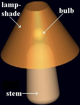
Another example is the application for designing table lamps. The first label is allocated to the lamp unit.
The root label cannot have brother labels. Consequently, various lamps in the framework allocation correspond to the sub-labels of the root label. This allows avoiding any confusion between table lamps in the data framework. Different lamp parts have different material, color and other attributes, so a child label of the lamp with the specified tags is allocated for each sub-unit of the lamp:
Label tags are chosen at will. They are only identifiers of the lamp parts. Now you can refine all units: by setting geometry, color, material and other information about the lamp or its parts to the specified label. This information is placed into special attributes of the label: the pure label contains no data – it is only a key to access data.
Remember that tags are private addresses without any meaning outside the data framework. It would, for instance, be an error to use part names as tags. These might change or be removed from production in next versions of the application, whereas the exact form of that part might be reused in your design, the part name could be integrated into the framework as an attribute.
So, after the user changes the lamp design, only corresponding attributes are changed, but the label structure is maintained. The lamp shape must be recreated by new attribute values and attributes of the lamp shape must refer to a new shape.
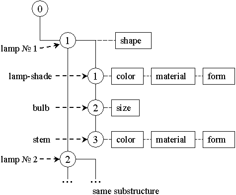
The previous figure shows the table-lamps document structure: each child of the root label contains a lamp shape attribute and refers to the sub-labels, which contain some design information about corresponding sub-units.
The data framework structure allows to create more complex structures: each lamp label sub-label may have children labels with more detailed information about parts of the table lamp and its components.
Note that the root label can have attributes too, usually global attributes: the name of the document, for example.
A tag is an integer, which identifies a label in two ways:
In relative identification, a label’s tag has a meaning relative to the father label only. For a specific label, you might, for example, have four child labels identified by the tags 2, 7, 18, 100. In using relative identification, you ensure that you have a safe scope for setting attributes.
In absolute identification, a label’s place in the data framework is specified unambiguously by a colon-separated list of tags of all the labels from the one in question to the root of the data framework. This list is called an entry. TDF_Tool::TagList allows retrieving the entry for a specific label.
In both relative and absolute identification, it is important to remember that the value of an integer has no intrinsic semantics whatsoever. In other words, the natural sequence that integers suggest, i.e. 0, 1, 2, 3, 4 ... – has no importance here. The integer value of a tag is simply a key.
The tag can be created in two ways:
As the names suggest, in random delivery, the tag value is generated by the system in a random manner. In user-defined delivery, you assign it by passing the tag as an argument to a method.
To append and return a new child label, you use TDF_TagSource::NewChild. In the example below, the argument level2, which is passed to NewChild, is a TDF_Label.
The other way to create a child label from a tag is by user delivery. In other words, you specify the tag, which you want your child label to have.
To retrieve a child label from a tag which you have specified yourself, you need to use TDF_Label::FindChild and TDF_Label::Tag as in the example below. Here, the integer 3 designates the tag of the label you are interested in, and the Boolean false is the value for the argument create. When this argument is set to false, no new child label is created.
The tag gives a persistent address to a label. The label – the semantics of the tag – is a place in the data framework where attributes, which contain data, are attached. The data framework is, in fact, a tree of labels with a root as the ultimate father label.
Label can not be deleted from the data framework, so, the structure of the data framework that has been created can not be removed while the document is opened. Hence any kind of reference to an existing label will be actual while an application is working with the document.
Labels can be created on any labels, compared with brother labels and retrieved. You can also find their depth in the data framework (depth of the root label is 0, depth of child labels of the root is 1 and so on), whether they have children or not, relative placement of labels, data framework of this label. The class TDF_Label offers the above services.
To create a new child label in the data framework using explicit delivery of tags, use TDF_Label::FindChild.
You could also use the same syntax but add the Boolean true as a value of the argument create. This ensures that a new child label will be created if none is found. Note that in the previous syntax, this was also the case since create is true by default.
You can retrieve child labels of your current label by iteration on the first level in the scope of this label.
You can also retrieve all child labels in every descendant generation of your current label by iteration on all levels in the scope of this label.
Using TDF_Tool::Entry with TDF_ChildIterator you can retrieve the entries of your current label’s child labels as well.
Retrieving the father label of a current label.
The label itself contains no data. All data of any type whatsoever – application or non-application – is contained in attributes. These are attached to labels, and there are different types for different types of data. OCAF provides many ready-to-use standard attributes such as integer, real, constraint, axis and plane. There are also attributes for topological naming, functions and visualization. Each type of attribute is identified by a GUID.
The advantage of OCAF is that all of the above attribute types are handled in the same way. Whatever the attribute type is, you can create new instances of them, retrieve them, attach them to and remove them from labels, "forget" and "remember" the attributes of a particular label.
To retrieve an attribute from a label, you use TDF_Label::FindAttribute. In the example below, the GUID for integer attributes, and INT, a handle to an attribute are passed as arguments to FindAttribute for the current label.
You can create a new instance of an attribute and retrieve its GUID. In the example below, a new integer attribute is created, and its GUID is passed to the variable guid by the method ID inherited from TDF_Attribute.
To attach an attribute to a label, you use TDF_Label::Add. Repetition of this syntax raises an error message because there is already an attribute with the same GUID attached to the current label.
TDF_Attribute::Label for INT then returns the label attach to which INT is attached.
Note. There is an exception from this rule for some sub-set of Standard attributes. See for details chapter 6.Standard Attributes.
You can test whether an attribute is attached to a label or not by using TDF_Attribute::IsA with the GUID of the attribute as an argument. In the example below, you test whether the current label has an integer attribute, and then, if that is so, how many attributes are attached to it. TDataStd_Integer::GetID provides the GUID argument needed by the method IsAttribute.
TDF_Attribute::HasAttribute tests whether there is an attached attribute, and TDF_Tool::NbAttributes returns the number of attributes attached to the label in question, e.g. current.
To remove an attribute from a label, you use TDF_Label::Forget with the GUID of the deleted attribute. To remove all attributes of a label, TDF_Label::ForgetAll.
If the set of existing and ready to use attributes implementing standard data types does not cover the needs of a specific data presentation task, the user can build his own data type and the corresponding new specific attribute implementing this new data type.
There are two ways to implement a new data type: create a new attribute (standard approach), or use the notion of User Attribute by means of a combination of standard attributes (alternative way)
In order to create a new attribute in the standard way, create a class inherited from TDF_Attribute and implement all purely virtual and necessary virtual methods:
Methods NewEmpty, Restore and Paste are used for the common transactions mechanism (Undo/Redo commands). If you don’t need this attribute to react to undo/redo commands, you can write only stubs of these methods, else you must call the Backup method of the TDF_Attribute class every time attribute fields are changed.
To enable possibility to save / restore the new attribute in XML format, do the following:
To enable possibility to save / restore the new attribute in binary format, do the following:
If you decided to use the alternative way (create a new attribute by means of UAttribute and a combination of other standard attributes), do the following:
Choosing the alternative way of implementation of new data types allows to forget about creating persistence classes for your new data type. Standard persistence classes will be used instead. Besides, this way allows separating the data and the methods for access to the data (interfaces). It can be used for rapid development in all cases when requirements to application performance are not very high.
Let’s study the implementation of the same data type in both ways by the example of transformation represented by gp_Trsf class. The class gp_Trsf defines the transformation according to the type (gp_TrsfForm) and a set of parameters of the particular type of transformation (two points or a vector for translation, an axis and an angle for rotation, and so on).
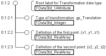
If the type of transformation is changed to rotation, the data tree looks like this:
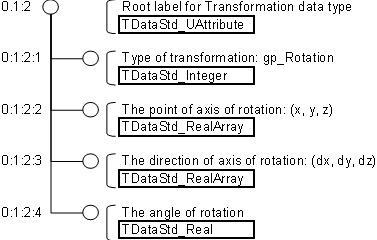
The attribute TDataStd_UAttribute with the chosen unique GUID identifies the data type. The interface class initialized by the label of this attribute allows access to the data container (type of transformation and the data of transformation according to the type).
As the identification of data is persistent, one document can reference data contained in another document, the referencing and referenced documents being saved in two separate files.
Lets look at the coffee machine application again. The coffee pot can be placed in one document. The coffee machine document then includes an occurrence — a positioned copy — of the coffee pot. This occurrence is defined by an XLink attribute (the external Link) which references the coffee pot of the first document (the XLink contains the relative path of the coffee pot document and the entry of the coffee pot data [0:1] ).
In this context, the end-user of the coffee machine application can open the coffee pot document, modify the geometry of, for example, the reservoir, and overwrite the document without worrying about the impact of the modification in the coffee machine document. To deal with this situation, OCAF provides a service which allows the application to check whether a document is up-to-date. This service is based on a modification counter included in each document: when an external link is created, a copy of the referenced document counter is associated to the XLink in the referencing document. Providing that each modification of the referenced document increments its own counter, we can detect that the referencing document has to be updated by comparing the two counters (an update function importing the data referenced by an XLink into the referencing document is also provided).
The Data Framework also provides a transaction mechanism inspired from database management systems: the data are modified within a transaction which is terminated either by a Commit if the modifications are validated or by an Abort if the modifications are abandoned — the data are then restored to the state it was in prior to the transaction. This mechanism is extremely useful for:
The transaction mechanism simply manages a backup copy of attributes. During a transaction, attributes are copied before their first modification. If the transaction is validated, the copy is destroyed. If the transaction is abandoned, the attribute is restored to its initial value (when attributes are added or deleted, the operation is simply reversed).
Transactions are document-centered, that is, the application starts a transaction on a document. So, modifying a referenced document and updating one of its referencing documents requires two transactions, even if both operations are done in the same working session.
Standard documents offer ready-to-use documents containing a TDF-based data framework. Each document can contain only one framework.
The documents themselves are contained in the instantiation of a class TDocStd_Application (or its descendant). This application manages the creation, storage and retrieval of documents.
You can implement undo and redo in your document, and refer from the data framework of one document to that of another one. This is done by means of external link attributes, which store the path and the entry of external links.
To sum up, standard documents alone provide access to the data framework. They also allow you to:
As a container for your data framework, you need a document, and your document must be contained in your application. This application will be a class TDocStd_Application or a class inheriting from it.
To create an application, use the following syntax.
To the application which you declared in the previous example (4.2.1), you must add the document doc as an argument of TDocStd_Application::NewDocument.
Here "NewDocumentFormat" is identifier of the format of your document. OCCT defines several standard formats, distinguishing by a set of supported OCAF attributes, and method of encoding (e.g. binary data or XML), described below. If your application defines specific OCAF attributes, you need to define your own format for it.
To retrieve the application containing your document, you use the syntax below.
The document contains your data framework, and allows you to retrieve this framework, recover its main label, save it in a file, and open or close this file.
To access the main label in the data framework, you use TDocStd_Document::Main as in the example below. The main label is the first child of the root label in the data framework, and has the entry 0:1.
To retrieve the document from a label in its data framework, you use TDocStd_Document::Get as in the example below. The argument label passed to this method is an instantiation of TDF_Label.
OCAF uses a customizable mechanism for storage of the documents. In order to use OCAF persistence to save and read your documents to / from the file, you need to define one or several formats in your application.
For that, use method TDocStd_Application::DefineFormat(), for instance:
This example defines format "NewDocumentFormat" with a default file extension "ndf", and instantiates drivers for reading and storing documents from and to that format. Either of the drivers can be null, in this case the corresponding action will not be supported for that format.
OCAF provides several standard formats, each covering some set of OCAF attributes:
| Format | Persistent toolkit | OCAF attributes covered |
|---|---|---|
| Legacy formats (read only) | ||
| OCC-StdLite | TKStdL | TKLCAF |
| MDTV-Standard | TKStd | TKLCAF + TKCAF |
| Binary formats | ||
| BinLOcaf | TKBinL | TKLCAF |
| BinOcaf | TKBin | TKLCAF + TKCAF |
| BinXCAF | TKBinXCAF | TKLCAF + TKCAF + TKXCAF |
| TObjBin | TKBinTObj | TKLCAF + TKTObj |
| XML formats | ||
| XmlLOcaf | TKXmlL | TKLCAF |
| XmlOcaf | TKXml | TKLCAF + TKCAF |
| XmlXCAF | TKXmlXCAF | TKLCAF + TKCAF + TKXCAF |
| TObjXml | TKXmlTObj | TKLCAF + TKTObj |
For convenience, these toolkits provide static methods DefineFormat() accepting handle to application. These methods allow defining corresponding formats easily, e.g.:
Use these toolkits as an example for implementation of persistence drivers for custom attributes, or new persistence formats.
The application can define several storage formats. On save, the format specified in the document (see TDocStd_Document::StorageFormat()) will be used (save will fail if that format is not defined in the application). On reading, the format identifier stored in the file is used and recorded in the document.
The alternative method to define formats is via usage of resource files. This method was used in earlier versions of OCCT and is considered as deprecated since version 7.1.0. This method allows loading persistence drivers on demand, using plugin mechanism.
To use this method, create your own application class inheriting from TDocStd_Application, and override method ResourcesName(). That method should return a string with a name of resource file, e.g. "NewDocumentFormat", which will contain a description of the format.
Then create that resource file and define the parameters of your format:
The GUIDs should be unique and correspond to the GUIDs supported by relevant plugin. You can use an existing plugins (see the table above) or create your own.
Finally, make a copy of the resource file "Plugin" from $CASROOT/src/StdResource and, if necessary, add the definition of your plugin in it, for instance:
In order to have these resource files loaded during the program execution, it is necessary to set two environment variables: CSF_PluginDefaults and CSF_NewFormatDefaults. For example, set the files in the directory MyApplicationPath/MyResources:
To save the document, make sure that its parameter StorageFormat() corresponds to one of the formats defined in the application, and use method TDocStd_Application::SaveAs, for instance:
To open the document from a file where it has been previously saved, you can use TDocStd_Application::Open as in the example below. The arguments are the path of the file and the document saved in this file.
To cut, copy and paste inside a document, use the class TDF_CopyLabel.
In fact, you must define a Label, which contains the temporary value of a cut or copy operation (say, in Lab_Clipboard). You must also define two other labels:
So we need a tool to copy all (or a part) of the content of a label and its sub-label, to another place defined by a label.
The filter is used to forbid copying a specified type of attribute.
You can also have a look at the class TDF_Closure, which can be useful to determine the dependencies of the part you want to cut from the document.
External links refer from one document to another. They allow you to update the copy of data framework later on.
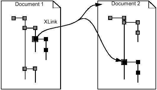
Note that documents can be copied with or without a possibility of updating an external link.
To copy a document with a possibility of updating it later, you use TDocStd_XLinkTool::CopyWithLink.
Now the target document has a copy of the source document. The copy also has a link in order to update the content of the copy if the original changes.
In the example below, something has changed in the source document. As a result, you need to update the copy in the target document. This copy is passed to TDocStd_XLinkTool::UpdateLink as the argument target.
You can also create a copy of the document with no link between the original and the copy. The syntax to use this option is TDocStd_XLinkTool::Copy. The copied document is again represented by the argument target, and the original – by source.
A topological attribute can be seen as a hook into the topological structure. It is possible to attach data to define references to it.
OCAF shape attributes are used for topology objects and their evolution access. All topological objects are stored in one TNaming_UsedShapes attribute at the root label of the data framework. This attribute contains a map with all topological shapes used in a given document.
The user can add the TNaming_NamedShape attribute to other labels. This attribute contains references (hooks) to shapes from the TNaming_UsedShapes attribute and an evolution of these shapes. The TNaming_NamedShape attribute contains a set of pairs of hooks: to the Old shape and to a New shape (see the following figure). It allows not only to get the topological shapes by the labels, but also to trace the evolution of the shapes and to correctly update dependent shapes by the changed one.
If a shape is newly created, then the old shape of a corresponding named shape is an empty shape. If a shape is deleted, then the new shape in this named shape is empty.
Different algorithms may dispose sub-shapes of the result shape at the individual labels depending on whether it is necessary to do so:
TNaming_NamedShape may contain a few pairs of hooks with the same evolution. In this case the topology shape, which belongs to the named shape is a compound of new shapes.
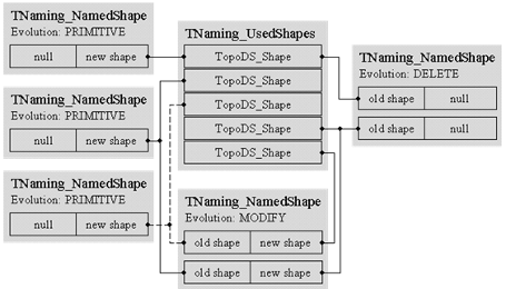
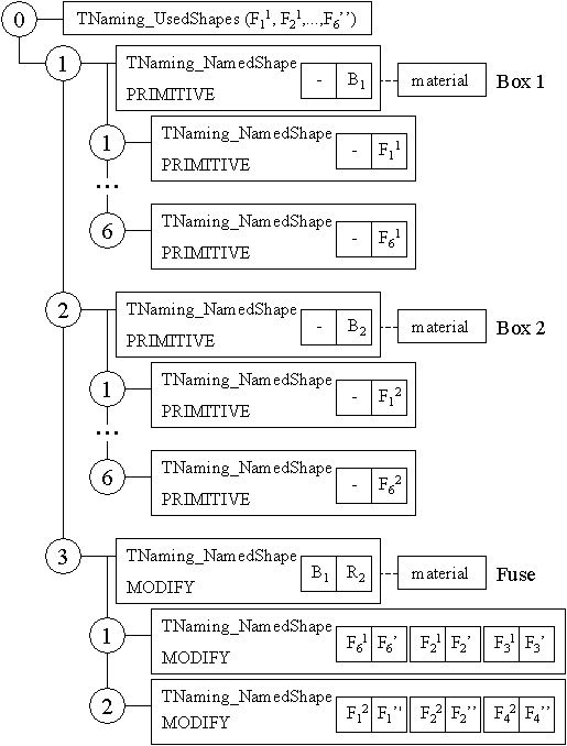
Consider the following example. Two boxes (solids) are fused into one solid (the result one). Initially each box was placed to the result label as a named shape, which has evolution PRIMITIVE and refers to the corresponding shape of the TNaming_UsedShapes map. The box result label has a material attribute and six child labels containing named shapes of Box faces.
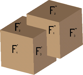
After the fuse operation a modified result is placed to a separate label as a named shape, which refers to the old shape (one of the boxes) and to the new shape resulting from the fuse operation, and has evolution MODIFY (see the following figure).
Named shapes, which contain information about modified faces, belong to the fuse result sub-labels:
This is necessary and sufficient information for the functionality of the right naming mechanism: any sub-shape of the result can be identified unambiguously by name type and set of labels, which contain named shapes:
After any modification of source boxes the application must automatically rebuild the naming entities: recompute the named shapes of the boxes (solids and faces) and fuse the resulting named shapes (solids and faces) that reference to the new named shapes.
When using TNaming_NamedShape to create attributes, the following fields of an attribute are filled:
Only pairs of shapes with equal evolution can be stored in one named shape.
The class TNaming_Builder allows creating a named shape attribute. It has a label of a future attribute as an argument of the constructor. Respective methods are used for the evolution and setting of shape pairs. If for the same TNaming_Builder object a lot of pairs of shapes with the same evolution are given, then these pairs would be placed in the resulting named shape. After the creation of a new object of the TNaming_Builder class, an empty named shape is created at the given label.
You can use the method TNaming_NamedShape::Evolution() to get the evolution of this named shape and the method TNaming_NamedShape::Get() to get a compound of new shapes of all pairs of this named shape.
More detailed information about the contents of the named shape or about the modification history of a topology can be obtained with the following:
The Topological Naming mechanism is based on 3 components:
To get the expected result the work of the three components should be synchronized and the rules of each component should be respected.
The "correct" history of a used modeling operation serves the basis of naming mechanism. It should be provided by the algorithm supporting the operation. The history content depends on the type of the topological result. The purpose of the history is to provide all entities for consistent and correct work of the Selection / Recomputation mechanism. The table below presents expected types of entities depending on the result type.
| Result type | Type of sub-shapes to be returned by history of algorithm | Comments |
|---|---|---|
| Solid or closed shell | Faces | All faces |
| Open shell or single face | Faces and edges of opened boundaries only | All faces plus all edges of opened boundaries |
| Closed wire | Edges | All edges |
| Opened wire | Edges and ending vertexes | All edges plus ending vertexes of the wire |
| Edge | Vertexes | Two vertexes are expected |
| Compound or CompSolid | To be used consequentially the above declared rule applied to all sub-shapes of the first level | Compound/CompSolid to be explored level by level until any the mentioned above types will be met |
The history should return (and track) only elementary types of sub-shapes, i.e. Faces, Edges and Vertexes, while other so-called aggregation types: Compounds, Shells, Wires, are calculated by Selection mechanism automatically.
There are some simple exceptions for several cases. For example, if the Result contains a seam edge – in conical, cylindrical or spherical surfaces – this seam edge should be tracked by the history and in addition should be defined before the types. All degenerated entities should be filtered and excluded from consideration.
All elements returned by the used algorithm according to the aforementioned rules should be put in the Data Framework (or OCAF document in other words) consequently in linear order under the so-called Result Label.
The "Result Label" is TDF_label used to keep the algorithm result Shape from TopoDS in NamedShape attribute. During loading sub-shapes of the result in Data Framework should be used the rules of chapter Registering shapes and their evolution. These rules are also applicable for loading the main shape, i.e. the resulting shape produced by the modeling algorithm.
When the Data Framework is filled with all impacted entities (including the data structures resulting from the current modeling operation and the data structures resulting from the previous modeling operations, on which the current operation depends) any sub-shape of the current result can be selected, i.e. the corresponding new naming data structures, which support this functionality, can be produced and kept in the Data Framework.
One of the user interfaces for topological naming is the class TNaming_Selector. It implements the above mentioned sub-shape "selection" functionality as an additional one. I.e. it can be used for:
The selector places a new named shape with evolution SELECTED to the given label. The selector creates a name of the selected shape, which is a unique description (data structure) of how to find the selected topology using as resources:
After any modification of a context shape and update of the corresponding naming structure, it is necessary to call method TNaming_Selector::Solve. If the naming structure, i.e. the above mentioned name, is correct, the selector automatically updates the selected sub-shape in the corresponding named shape, else it fails.
The class TNaming_Tool provides a toolkit to read current data contained in the attribute.
If you need to create a topological attribute for existing data, use the method NamedShape.
Topological naming is a mechanism of Open CASCADE aimed to keep reference to the selected shape. If, for example, we select a vertex of a solid shape and “ask” the topological naming to keep reference to this vertex, it will refer to the vertex whatever happens with the shape (translations, scaling, fusion with another shape, etc.).
Let us consider an example: imagine a wooden plate. The job is to drive several nails in it:
There may be several nails with different size and position. A Hammer should push each Nail exactly in the center point of the top surface. For this the user does the following:
The job is done. The application should do the rest – the Hammer calculates a center point for each selected surface of the Nail and “strikes” each Nail driving it into the wooden plate.
What happens if the user changes the position of some Nails? How will the Hammer know about it? It keeps reference to the surface of each Nail. However, if a Nail is relocated, the Hammer should know the new position of the selected surface. Otherwise, it will “strike” at the old position (keep the fingers away!)…
Topological naming mechanism should help the Hammer to obtain the relocated surfaces. The Hammer “asks” the mechanism to “resolve” the selected shapes by calling method TNaming_Selection::Solve() and the mechanism “returns” the modified surfaces located at the new position by calling TNaming_Selector::NamedShape().
The topological naming is represented as a “black box” in the example above. Now it is time to make the box a little more “transparent”.
The application contains 3 functions:
Each function gives the topological naming some hints how to “re-solve” the selected sub-shapes:
How does it work?
The job is done.
P.S. Let us say a few words about a little more complicated case – selection of a wire of the top face. Its topological name is an “intersection” of two faces. We remember that the Nail puts only faces under its label. So, the selected wire will represent an “intersection” of the top face and the conic face keeping the “head” of the nail. Another example is a selected vertex. Its unique name may be represented as an “intersection” of three or even more faces (depends on the shape).
Standard attributes are ready-to-use attributes, which allow creating and modifying attributes for many basic data types. They are available in the packages TDataStd, TDataXtd and TDF. Each attribute belongs to one of four types:
All attributes inherit class TDF_Attribute, so, each attribute has its own GUID and standard methods for attribute creation, manipulation, getting access to the data framework.
By default only one attribute of the same type on the same lable is supported. For example, you can set only one TDataStd_Real attribute on the same label. This limitation was removed for some predefined sub-set of standard attributes by adding so called 'user defined ID' feature to the attribute. The listed below attributes received this new feature:
See for details paragraph 6.4.
To access the GUID of an attribute, you can use two methods:
To find an attribute attached to a specific label, you use the GUID of the attribute type you are looking for. This information can be found using the method GetID and the method Find for the label as follows:
It is usual to create standard named methods for the attributes:
When you start to design an application based on OCAF, usually it is necessary to choose, which attribute will be used for allocation of data in the OCAF document: standard or newly-created?
It is possible to describe any model by means of standard OCAF attributes. However, it is still a question if this description will be efficient in terms of memory and speed, and, at the same time, convenient to use.
This depends on a particular model.
OCAF imposes the restriction that only one attribute type may be allocated to one label. It is necessary to take into account the design of the application data tree. For example, if a label should possess several double values, it is necessary to distribute them through several child sub-labels or use an array of double values.
Let us consider several boundary implementations of the same model in OCAF tree and analyze the advantages and disadvantages of each approach.
Below are described two different model implementations: one is based on standard OCAF attributes and the other is based on the creation of a new attribute possessing all data of the model.
A load is distributed through the shape. The measurements are taken at particular points defined by (x, y and z) co-ordinates. The load is represented as a projection onto X, Y and Z axes of the local co-ordinate system at each point of measurement. A matrix of transformation is needed to convert the local co-ordinate system to the global one, but this is optional.
So, we have 15 double values at each point of measurement. If the number of such points is 100 000, for example, it means that we have to store 1 500 000 double values in the OCAF document.
The first approach consists in using standard OCAF attributes. Besides, there are several variants of how the standard attributes may be used:
Certainly, other variants are also possible.
The first approach to allocation of all data represented as one array of double values saves initial memory and is easy to implement. But access to the data is difficult because the values are stored in a flat array. It will be necessary to implement a class with several methods giving access to particular fields like the measurement points, loads and so on.
If the values may be edited in the application, it means that the whole array will be backed-up on each edition. The memory usage will increase very fast! So, this approach may be considered only in case of non-editable data.
Let’s consider the allocation of data of each measurement point per label (the second case). In this case we create 100 000 labels – one label for each measurement point and attach an array of double values to these labels:
Now edition of data is safer as far as memory usage is concerned. Change of value for one measurement point (any value: point co-ordinates, load, and so on) backs-up only one small array of double values. But this structure (tree) requires more memory space (additional labels and attributes).
Besides, access to the values is still difficult and it is necessary to have a class with methods of access to the array fields.
The third case of allocation of data through OCAF tree is represented below:
In this case sub-labels are involved and we can easily access the values of each measurement point, load or matrix. We don’t need an interface class with methods of access to the data (if it exists, it would help to use the data structure, but this is optional).
On the one hand, this approach requires more memory for allocation of the attributes (arrays of double values). On the other hand, it saves memory during the edition of data by backing-up only the small array containing the modified data. So, if the data is fully modifiable, this approach is more preferable.
Before making a conclusion, let’s consider the same model implemented through a newly created OCAF attribute.
For example, we might allocate all data belonging to one measurement point as one OCAF attribute. In this case we implement the third variant of using the standard attributes (see picture 3), but we use less memory (because we use only one attribute instead of three):
The second variant of using standard OCAF attributes still has drawbacks: when data is edited, OCAF backs-up all values of the measurement point.
Let’s imagine that we have some non-editable data. It would be better for us to allocate this data separately from editable data. Back-up will not affect non-editable data and memory will not increase so much during data edition.
When deciding which variant of data model implementation to choose, it is necessary to take into account the application response time, memory allocation and memory usage in transactions.
Most of the models may be implemented using only standard OCAF attributes. Some other models need special treatment and require implementation of new OCAF attributes.
The listed above attributes allow to set at the same Label as many attributes of the same type as you want thanks to specific user's ID. Let's consider it on the example of the TDataStd_Real attribute. The previous version of the attribute allowed to set the attribute using static method Set in next way:
This is a default form which is kept by the attribute. It uses the default GUID for the attribute identification - TDataStd_Real::GetID(). In case if you want to use the new feature (user defined Real attribute), for example to define several attributes which should keep a value of the same type - Standard_Real, but to be associated with different user's notions (or objects) the new static method Set should be used. In our example we will define two Real attributes which presents two customer's objects - Density and Volume and will be put on the same Label.
You can create a new instance of an attribute with user define GUID and add it to label in two ways.
Standard visualization attributes implement the Application Interactive Services (see Visualization User's Guide). in the context of Open CASCADE Technology Application Framework. Standard visualization attributes are AISViewer and Presentation and belong to the TPrsStd package.
The class TPrsStd_AISViewer allows you to define an interactive viewer attribute. There may be only one such attribute per one data framework and it is always placed to the root label. So, it could be set or found by any label ("access label") of the data framework. Nevertheless the default architecture can be easily extended and the user can manage several Viewers per one framework by himself.
To initialize the AIS viewer as in the example below, use method Find.
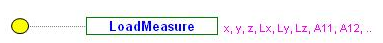
The class TPrsStd_AISPresentation allows you to define the visual presentation of document labels contents. In addition to various visual fields (color, material, transparency, isDisplayed, etc.), this attribute contains its driver GUID. This GUID defines the functionality, which will update the presentation every time when needed.
The abstract class TPrsStd_Driver allows you to define your own driver classes. Simply redefine the Update method in your new class, which will rebuild the presentation.
If your driver is placed to the driver table with the unique driver GUID, then every time the viewer updates presentations with a GUID identical to your driver’s GUID, the Update method of your driver for these presentations must be called:
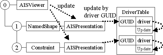
As usual, the GUID of a driver and the GUID of a displayed attribute are the same.
You frequently need a container for different presentation drivers. The class TPrsStd_DriverTable provides this service. You can add a driver to the table, see if one is successfully added, and fill it with standard drivers.
To fill a driver table with standard drivers, first initialize the AIS viewer as in the example above, and then pass the return value of the method InitStandardDrivers to the driver table returned by the method Get. Then attach a TNaming_NamedShape to a label and set the named shape in the presentation attribute using the method Set. Then attach the presentation attribute to the named shape attribute, and the AIS_InteractiveObject, which the presentation attribute contains, will initialize its drivers for the named shape. This can be seen in the example below.
Example
Function services aggregate data necessary for regeneration of a model. The function mechanism – available in the package TFunction – provides links between functions and any execution algorithms, which take their arguments from the data framework, and write their results inside the same framework.
When you edit any application model, you have to regenerate the model by propagating the modifications. Each propagation step calls various algorithms. To make these algorithms independent of your application model, you need to use function services.
Take, for example, the case of a modeling sequence made up of a box with the application of a fillet on one of its edges. If you change the height of the box, the fillet will need to be regenerated as well.
The class TFunction_Function is an attribute, which stores a link to a function driver in the data framework. In the static table TFunction_DriverTable correspondence links between function attributes and drivers are stored.
You can write your function attribute, a driver for such attribute, which updates the function result in accordance to a given map of changed labels, and set your driver with the GUID to the driver table.
Then the solver algorithm of a data model can find the Function attribute on a corresponding label and call the Execute driver method to update the result of the function.
For updating algorithm optimization, each function driver has access to the TFunction_Logbook object that is a container for a set of touched, impacted and valid labels. Using this object a driver gets to know which arguments of the function were modified.
An application must implement its functions, function drivers and the common solver for parametric model creation. For example, check the following model:
The procedure of its creation is as follows:
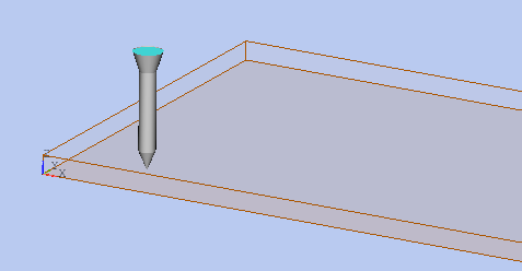
Let us describe the usage of the Function Mechanism of Open CASCADE Application Framework on a simple example. This example represents a "nail" composed by a cone and two cylinders of different radius and height:
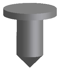
These three objects (a cone and two cylinders) are independent, but the Function Mechanism makes them connected to each other and representing one object – a nail. The object "nail" has the following parameters:
So, the cylinders depend on the cone and the cone parameters define the size of the nail.
It means that re-positioning the cone (changing its apex point) moves the nail, the change of the radius of the cone produces a thinner or thicker nail, and the change of the height of the cone shortens or prolongates the nail. It is suggested to examine the programming steps needed to create a 3D parametric model of the "nail".
The first step consists in model data allocation in the OCAF tree. In other words, it is necessary to decide where to put the data.
In this case, the data can be organized into a simple tree using references for definition of dependent parameters:
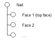
Nail
The "nail" object has three sub-leaves in the tree: the cone and two cylinders.
The cone object is independent.
The long cylinder representing a "stem" of the nail refers to the corresponding parameters of the cone to define its own data (position, radius and height). It means that the long cylinder depends on the cone.
The parameters of the head cylinder may be expressed through the cone parameters only or through the cone and the long cylinder parameters. It is suggested to express the position and the radius of the head cylinder through the position and the radius of the long cylinder, and the height of the head cylinder through the height of the cone. It means that the head cylinder depends on the cone and the long cylinder.
The interfaces of the data model are responsible for dynamic creation of the data tree of the represented at the previous step, data modification and deletion.
The interface called INail should contain the methods for creation of the data tree for the nail, setting and getting of its parameters, computation, visualization and removal.
This method of the interface creates a data tree for the nail at a given leaf of OCAF data tree.
It creates three sub-leaves for the cone and two cylinders and allocates the necessary data (references at the sub-leaves of the long and the head cylinders).
It sets the default values of position, radius and height of the nail.
The nail has the following user parameters:
The values of the position and the radius of the nail are defined for the cone object data. The height of the cone is recomputed as 2 * heights of nail and divided by 9.
The Function Mechanism is responsible for re-computation of the nail. It will be described in detail later in this document.
A data leaf consists of the reference to the location of the real data and a real value defining a coefficient of multiplication of the referenced data.
For example, the height of the long cylinder is defined as a reference to the height of the cone with coefficient 3. The data leaf of the height of the long cylinder should contain two attributes: a reference to the height of cone and a real value equal to 3.
The shape resulting of the nail function can be displayed using the standard OCAF visualization mechanism.
To automatically erase the nail from the viewer and the data tree it is enough to clean the nail leaf from attributes.
The nail is defined by four functions: the cone, the two cylinders and the nail function. The function of the cone is independent. The functions of the cylinders depend on the cone function. The nail function depends on the results of all functions:
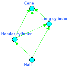
Computation of the model starts with the cone function, then the long cylinder, after that the header cylinder and, finally, the result is generated by the nail function at the end of function chain.
The Function Mechanism of Open CASCADE Technology creates this graph of dependencies and allows iterating it following the dependencies. The only thing the Function Mechanism requires from its user is the implementation of pure virtual methods of TFunction_Driver:
These methods give the Function Mechanism the information on the location of arguments and results of the function and allow building a graph of functions. The class TFunction_Iterator iterates the functions of the graph in the execution order.
The pure virtual method TFunction_Driver::Execute() calculating the function should be overridden.
The method ::MustExecute() calls the method ::Arguments() of the function driver and ideally this information (knowledge of modification of arguments of the function) is enough to make a decision whether the function should be executed or not. Therefore, this method usually shouldn’t be overridden.
The cone and cylinder functions differ only in geometrical construction algorithms. Other parameters are the same (position, radius and height).
It means that it is possible to create a base class – function driver for the three functions, and two descendant classes producing: a cone or a cylinder.
For the base function driver the methods ::Arguments() and ::Results() will be overridden. Two descendant function drivers responsible for creation of a cone and a cylinder will override only the method ::Execute().
The method ::Arguments() of the function driver of the nail returns the results of the functions located under it in the tree of leaves. The method ::Execute() just collects the results of the functions and makes one shape – a nail.
This way the data model using the Function Mechanism is ready for usage. Do not forget to introduce the function drivers for a function driver table with the help of TFunction_DriverTable class.
This is an example of the code for iteration and execution of functions.
This is an example of the code for a cylinder function driver. To make the things clearer, the methods ::Arguments() and ::Results() from the base class are also mentioned.
Writing and reading XML files in OCCT is provided by LDOM package, which constitutes an integral part of XML OCAF persistence, which is the optional component provided on top of Open CASCADE Technology.
The Light DOM (LDOM) package contains classes maintaining a data structure whose main principles conform to W3C DOM Level 1 Recommendations. The purpose of these classes as required by XML OCAF persistence schema is to:
This package covers the functionality provided by numerous products known as "DOM parsers". Unlike most of them, LDOM was specifically developed to meet the following requirements:
Both these requirements are important when XML files are processed by applications if these files are relatively large (occupying megabytes and even hundreds of megabytes). To meet the requirements, some limitations were imposed on the DOM Level 1 specification; these limitations are insignificant in applications like OCAF. Some of these limitations can be overridden in the course of future developments. The main limitations are:
LDOM is dependent on Kernel OCCT classes only. Therefore, it can be used outside OCAF persistence in various algorithms where DOM/XML support may be required.
The drivers for document storage and retrieval manage conversion between a transient OCAF Document in memory and its persistent reflection in a container (disk, memory, network). For XML Persistence, they are defined in the package XmlDrivers.
The main methods (entry points) of these drivers are:
The most common case (which is implemented in XML Persistence) is writing/reading document to/from a regular OS file. Such conversion is performed in two steps:
First it is necessary to convert the transient document into another form (called persistent), suitable for writing into a file, and vice versa. In XML Persistence LDOM_Document is used as the persistent form of an OCAF Document and the DOM_Nodes are the persistent objects. An OCAF Document is a tree of labels with attributes. Its transformation into a persistent form can be functionally divided into two parts:
The driver for each attribute is selected from a table of drivers, either by attribute type (on storage) or by the name of the corresponding DOM_Element (on retrieval). The table of drivers is created by by methods XmlDrivers_DocumentStorageDriver::AttributeDrivers() and XmlDrivers_DocumentRetrievalDriver::AttributeDrivers().
Then the persistent document is written into a file (or read from a file). In standard persistence Storage and FSD packages contain classes for writing/reading the persistent document into a file. In XML persistence LDOMParser and LDOM_XmlWriter are used instead.
Usually, the library containing document storage and retrieval drivers is loaded at run time by a plugin mechanism. To support this in XML Persistence, there is a plugin XmlPlugin and a Factory() method in the XmlDrivers package. This method compares passed GUIDs with known GUIDs and returns the corresponding driver or generates an exception if the GUID is unknown.
The application defines which GUID is needed for document storage or retrieval and in which library it should be found. This depends on document format and application resources. Resources for XML Persistence and also for standard persistence are found in the StdResource unit. They are written for the XmlOcaf document format.
There is one attribute driver for XML persistence for each transient attribute from a set of standard OCAF attributes, with the exception of attribute types, which are never stored (pure transient). Standard OCAF attributes are collected in six packages, and their drivers also follow this distribution. Driver for attribute T*_* is called XmlM*_*. Conversion between transient and persistent form of attribute is performed by two methods Paste() of attribute driver.
XmlMDF_ADriver is the root class for all attribute drivers.
At the beginning of storage/retrieval process, one instance of each attribute driver is created and appended to driver table implemented as XmlMDF_ADriverTable. During OCAF Data storage, attribute drivers are retrieved from the driver table by the type of attribute. In the retrieval step, a data map is created linking names of DOM_Elements and attribute drivers, and then attribute drivers are sought in this map by DOM_Element qualified tag names.
Every transient attribute is saved as a DOM_Element (root element of OCAF attribute) with attributes and possibly sub-nodes. The name of the root element can be defined in the attribute driver as a string passed to the base class constructor. The default is the attribute type name. Similarly, namespace prefixes for each attribute can be set. There is no default value, but it is possible to pass NULL or an empty string to store attributes without namespace prefixes.
The basic class XmlMDF_ADriver supports errors reporting via the method WriteMessage(const TCollection_ExtendedString&). It sends a message string to its message driver which is initialized in the constructor with a Handle(CDM_MessageDriver) passed from the application by Document Storage/Retrieval Driver.
Every XML Document has one root element, which may have attributes and contain other nodes. In OCAF XML Documents the root element is named "document" and has attribute "format" with the name of the OCAF Schema used to generate the file. The standard XML format is "XmlOcaf". The following elements are sub-elements of <document> and should be unique entries as its sub-elements, in a specific order. The order is:
In XML documents, OCAF attributes are elements whose name identifies the OCAF attribute type. These elements may have a simple (string or number) or complex (sub-elements) structure, depending on the architecture of OCAF attribute. Every XML type for OCAF attribute possesses a unique positive integer "id" XML attribute identifying the OCAF attribute throughout the document. To ensure "id" uniqueness, the attribute name "id" is reserved and is only used to indicate and identify elements which may be referenced from other parts of the OCAF XML document. For every standard OCAF attribute, its XML name matches the name of a C++ class in Transient data model. Generally, the XML name of OCAF attribute can be specified in the corresponding attribute driver. XML types for OCAF attributes are declared with XML W3C Schema in a few XSD files where OCAF attributes are grouped by the package where they are defined.
The following example is a sample text from an XML file obtained by storing an OCAF document with two labels (0: and 0:2) and two attributes – TDataStd_Name (on label 0:) and TNaming_NamedShape (on label 0:2). The <shapes> section contents are replaced by an ellipsis.
The XML Schema defines the class of a document.
The full structure of OCAF XML documents is described as a set of XML W3C Schema files with definitions of all XML element types. The definitions provided cannot be overridden. If any application defines new persistence schemas, it can use all the definitions from the present XSD files but if it creates new or redefines existing types, the definition must be done under other namespace(s).
There are other ways to declare XML data, different from W3C Schema, and it should be possible to use them to the extent of their capabilities of expressing the particular structure and constraints of our XML data model. However, it must be noted that the W3C Schema is the primary format for declarations and as such, it is the format supported for future improvements of Open CASCADE Technology, including the development of specific applications using OCAF XML persistence.
The Schema files (XSD) are intended for two purposes:
The Schema definitions are not used by OCAF XML Persistence algorithms when saving and restoring XML documents. There are internal checks to ensure validity when processing every type of data.
Both the XML format and the XML OCAF persistence code are extensible in the sense that every new development can reuse everything that has been created in previous projects. For the XML format, this extensibility is supported by assigning names of XML objects (elements) to different XML Namespaces. Hence, XML elements defined in different projects (in different persistence libraries) can easily be combined into the same XML documents. An example is the XCAF XML persistence built as an extension to the Standard OCAF XML persistence [File XmlXcaf.xsd]. For the correct management of Namespaces it is necessary to:
In C++, the application behavior is implemented in virtual functions redefined in these derived classes. This is known as overriding.
At the beginning of your development, you first define an application class by inheriting from the Application abstract class. You only have to create and determine the resources of the application for specifying the format of your documents (you generally use the standard one) and their file extension.
Then, you design the application data model by organizing attributes you choose among those provided with OCAF. You can specialize these attributes using the User attribute. For example, if you need a reflection coefficient, you aggregate a User attribute identified as a reflection coefficient with a Real attribute containing the value of the coefficient (as such, you don't define a new class).
If you need application specific data not provided with OCAF, for example, to incorporate a finite element model in the data structure, you define a new attribute class containing the mesh, and you include its persistent homologue in a new file format.
Once you have implemented the commands which create and modify the data structure according to your specification, OCAF provides you, without any additional programming:
Finally, you develop the application's graphical user interface using the toolkit of your choice, for example:
You can also implement the user interface in the Java language using the Swing-based Java Application Desktop component (JAD) provided with OCAF.
There are four sample files provided in the directory 'OpenCasCade/ros/samples/ocafsamples'. They present typical actions with OCAF services (mainly for newcomers). The method Sample() of each file is not dedicated for execution 'as is', it is rather a set of logical actions using some OCAF services.
This sample contains templates for typical actions with the following standard OCAF attributes:
This sample contains template for the following typical actions:
This sample contains template for the following typical actions:
This sample contains template for typical actions with OCAF Topological Naming services. The following scenario is used:
 1.8.13