|
Open CASCADE Technology
7.1.0
|
|
|
Open CASCADE Technology
7.1.0
|
|
This document provides a comprehensive description of the Boolean Operation Algorithm (BOA) as it is implemented in Open CASCADE Technology. The Boolean Component contains:
GFA is the base algorithm for BOA, PA, SA.
GFA has a history-based architecture designed to allow using OCAF naming functionality. The architecture of GFA is expandable, that allows creating new algorithms basing on it.
The Boolean operator provides the operations (Common, Fuse, Cut) between two groups: Objects and Tools. Each group consists of an arbitrary number of arguments in terms of TopoDS_Shape.
The operator can be represented as:
RB=Bj (G1, G2),
where:
Note There is an operation Cut21, which is an extension for forward Cut operation, i.e Cut21=Cut(G2, G1).
The General fuse operator can be applied to an arbitrary number of arguments in terms of TopoDS_Shape.
The GFA operator can be represented as:
RGF = GF (S1, S2 ... Sn),
where
The result of the Boolean operator, RB, can be obtained from RGF.
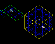
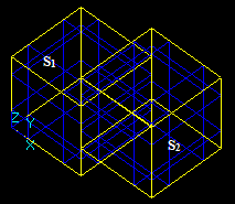
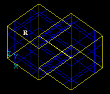
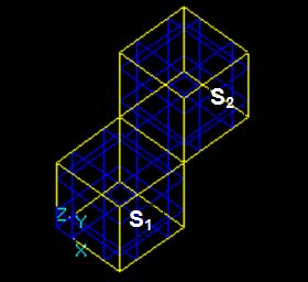
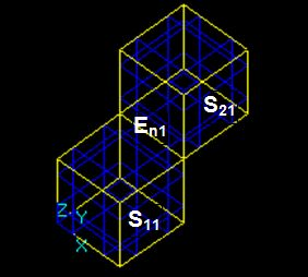
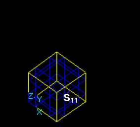
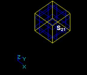
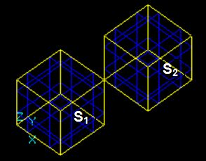
For example, for two arguments S1 and S2 the result RGF is
RGF = GF (S1, S2) = Sp1 + Sp2 + Sp12

This Figure shows that
RGF=GF (S1, S2) = Bfuse = Bcommon+ Bcut12+ Bcut21.
The fact that RGF contains the components of RB allows considering GFA as the general case of BOA. So it is possible to implement BOA as a subclass of GFA.
The Partition operator can be applied to an arbitrary number of arguments in terms of TopoDS_Shape. The arguments are divided on two groups: Objects, Tools. The result of PA contains all parts belonging to the Objects but does not contain the parts that belongs to the Tools only.
The PA operator can be represented as follows:
RPA=PA (G1, G2), where:
The result RPA can be obtained from RGF .
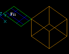
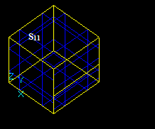
For example, for two arguments S1 and S2 the result RPA is
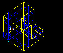
RPA=PA(S1,S2)=Sp1+Sp12.
In case when all arguments of the PA are Objects (no Tools), the result of PA is equivalent to the result of GFA.
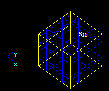
For example, when G1 consists of shapes S1 and S2 the result of RPA is
RPA=PA(S1, S2) = Sp1 + Sp2 + Sp12 = GF (S1, S2)
The fact that the RGF contains the components of RPA allows considering GFA as the general case of PA. Thus, it is possible to implement PA as a subclass of GFA.
The Section operator SA can be applied to arbitrary number of arguments in terms of TopoDS_Shape. The result of SA contains vertices and edges in accordance with interferences between the arguments The SA operator can be represented as follows: RSA=SA(S1, S2… Sn), where
GFA, BOA, PA and SA have the same Data Structure (DS). The main goal of the Data Structure is to store all necessary information for input data and intermediate results.
The operators consist of two main parts:
As it follows from the definition of operator results, the main differences between GFA, BOA, PA and SA are in the Building Part. The Intersection Part is the same for the algorithms.
This chapter provides the background terms and definitions that are necessary to understand how the algorithms work.
There are two groups of interferences.
At first, each shape having a boundary representation (vertex, edge, face) has an internal value of geometrical tolerance. The shapes interfere with each other in terms of their tolerances. The shapes that have a boundary representation interfere when there is a part of 3D space where the distance between the underlying geometry of shapes is less or equal to the sum of tolerances of the shapes. Three types of shapes: vertex, edge and face – produce six types of BRep interferences:
At second, there are interferences that occur between a solid Z1 and a shape S2 when Z1 and S2 have no BRep interferences but S2 is completely inside of Z1. These interferences are Non-BRep interferences. There are four possible cases:
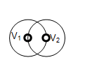
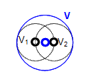
For two vertices Vi and Vj, the distance between their corresponding 3D points is less than the sum of their tolerances Tol(Vi) and Tol(Vj).

The result is a new vertex Vn with 3D point Pn and tolerance value Tol(Vn).
The coordinates of Pn and the value Tol(Vn) are computed as the center and the radius of the sphere enclosing the tolerance spheres of the source vertices (V1, V2).
For a vertex Vi and an edge Ej, the distance D between 3D point of the vertex and its projection on the 3D curve of edge Ej is less or equal than sum of tolerances of vertex Tol(Vi) and edge Tol(Ej).

The result is vertex Vi with the corresponding tolerance value Tol(Vi)=Max(Tol(Vi), D+Tol(Ej)), where D = distance (Pi, PPi);
and parameter ti of the projected point PPi on 3D curve Cj of edge Ej.
For a vertex Vi and a face Fj the distance D between 3D point of the vertex and its projection on the surface of the face is less or equal than sum of tolerances of the vertex Tol(Vi) and the face Tol(Fj).

The result is vertex Vi with the corresponding tolerance value Tol(Vi)=Max(Tol(Vi), D+Tol(Fj)), where D = distance (Pi, PPi)
and parameters ui, vi of the projected point PPi on surface Sj of face Fj.
For two edges Ei and Ej (with the corresponding 3D curves Ci and Cj) there are some places where the distance between the curves is less than (or equal to) sum of tolerances of the edges.
Let us examine two cases:
In the first case two edges have one or several common parts of 3D curves in terms of tolerance.

The results are:
In the second case two edges have one or several common points in terms of tolerance.

The coordinates of Pn and the value Tol(Vn) are computed as the center and the radius of the sphere enclosing the tolerance spheres of the corresponding nearest points Pi, Pj of 3D curves Ci, Cj of source edges Ei, Ej.
For an edge Ei (with the corresponding 3D curve Ci) and a face Fj (with the corresponding 3D surface Sj) there are some places in 3D space, where the distance between Ci and surface Sj is less than (or equal to) the sum of tolerances of edge Ei and face Fj.
Let us examine two cases:
In the first case Edge Ei and Face Fj have one or several common parts in terms of tolerance.

The result is a parametric range [ti1, ti2] for the 3D curve Ci of the edge Ei.
In the second case Edge Ei and Face Fj have one or several common points in terms of tolerance.

The result is a new vertex Vn with 3D point Pn and tolerance value Tol(Vn).
The coordinates of Pn and the value Tol(Vn) are computed as the center and the radius of the sphere enclosing the tolerance spheres of the corresponding nearest points Pi, Pj of 3D curve Ci and surface Sj of source edges Ei, Fj.
For a face Fi and a face Fj (with the corresponding surfaces Si and Sj) there are some places in 3D space, where the distance between the surfaces is less than (or equal to) sum of tolerances of the faces.

In the first case the result contains intersection curves Cijk (k = 0, 1, 2…kN, where kN is the number of intersection curves with corresponding values of tolerances Tol(Cijk).

In the second case Face Fi and face Fj have one or several new vertices Vijm, where m=0,1,2, ... mN, mN is the number of intersection points.
The coordinates of a 3D point Pijm and the value Tol(Vijm) are computed as the center and the radius of the sphere enclosing the tolerance spheres of the corresponding nearest points Pi, Pj of the surface Si, Sj of source shapes Fi, Fj.
For a vertex Vi and a solid Zj there is Vertex/Solid interference if the vertex Vi has no BRep interferences with any sub-shape of Zj and Vi is completely inside the solid Zj.
For an edge Ei and a solid Zj there is Edge/Solid interference if the edge Ei and its sub-shapes have no BRep interferences with any sub-shape of Zj and Ei is completely inside the solid Zj.
For a face Fi and a solid Zj there is Face/Solid interference if the face Fi and its sub-shapes have no BRep interferences with any sub-shape of Zj and Fi is completely inside the solid Zj.
For a solid Zi and a solid Zj there is Solid/Solid interference if the solid Zi and its sub-shapes have no BRep interferences with any sub-shape of Zj and Zi is completely inside the solid Zj.
The interferences between shapes are computed on the basis of increasing of the dimension value of the shape in the following order:
This order allows avoiding the computation of redundant interferences between upper-level shapes Si and Sj when there are interferences between lower sub-shapes Sik and Sjm.
The result of interferences of the type Vertex/Edge, Edge/Edge and Edge/Face in most cases is a vertex (new or old) lying on an edge.
The result of interferences of the type Face/Face in most cases is intersection curves, which go through some vertices lying on the faces.
The position of vertex Vi on curve C can be defined by a value of parameter ti of the 3D point of the vertex on the curve. Pave PVi on curve C is a structure containing the vertex Vi and correspondent value of the parameter ti of the 3D point of the vertex on the curve. Curve C can be a 3D or a 2D curve.

Two paves PV1 and PV2 on the same curve C can be compared using the parameter value
The usage of paves allows binding of the vertex to the curve (or any structure that contains a curve: edge, intersection curve).
A set of paves PVi (i=1, 2...nPV), where nPV is the number of paves] of curve C can be sorted in the increasing order using the value of parameter t on curve C.
A pave block PBi is a part of the object (edge, intersection curve) between neighboring paves.

Any finite source edge E has at least one pave block that contains two paves PVb and PVe:
Pave block PV of curve C is bounded by vertices V1 and V2 with tolerance values Tol(V1) and Tol(V2). Curve C has its own tolerance value Tol(C):

The theoretical parametric range of the pave block is [t1C, t2C].
The positions of the vertices V1 and V2 of the pave block can be different. The positions are determined by the following conditions:
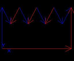
The Figure shows that each tolerance sphere of a vertex can reduce the parametric range of the pave block to a range [t1S, t2S]. The range [t1S, t2S] is the shrunk range of the pave block.
The shrunk range of the pave block is the part of 3D curve that can interfere with other shapes.
The interferences of the type Edge/Edge, Edge/Face produce results as common parts.
In case of Edge/Edge interference the common parts are pave blocks that have different base edges.

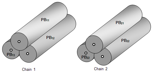
If the pave blocks PB1, PB2…PBNbPB , where NbPB is the number of pave blocks have the same bounding vertices and geometrically coincide, the pave blocks form common block CB.
In case of Edge/Face interference the common parts are pave blocks lying on a face(s).

If the pave blocks PBi geometrically coincide with a face Fj, the pave blocks form common block CB.
In general case a common block CB contains:
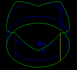
The structure FaceInfo contains the following information:

In the figure, for face F1:
Data Structure (DS) is used to:
This information includes:
Data Structure is implemented in the class BOPDS_DS.
The arguments are shapes (in terms of TopoDS_Shape):
| No | Type | Index of Type |
|---|---|---|
| 1 | COMPOUND | 0 |
| 2 | COMPSOLID | 1 |
| 3 | SOLID | 2 |
| 4 | SHELL | 3 |
| 5 | FACE | 4 |
| 6 | WIRE | 5 |
| 7 | EDGE | 6 |
| 8 | VERTEX | 7 |
The information about Shapes is stored in structure BOPDS_ShapeInfo. The objects of type BOPDS_ShapeInfo are stored in the container of array type. The array allows getting the access to the information by an index (DS index). The structure BOPDS_ShapeInfo has the following contents:
| Name | Contents |
|---|---|
| myShape | Shape itself |
| myType | Type of shape |
| myBox | 3D bounding box of the shape |
| mySubShapes | List of DS indices of sub-shapes |
| myReference | Storage for some auxiliary information |
| myFlag | Storage for some auxiliary information |
The information about interferences is stored in the instances of classes that are inherited from class BOPDS_Interf.
| Name | Contents |
|---|---|
| BOPDS_Interf | Root class for interference |
| Index1 | DS index of the shape 1 |
| Index2 | DS index of the shape 2 |
| BOPDS_InterfVV | Storage for Vertex/Vertex interference |
| BOPDS_InterfVE | Storage for Vertex/Edge interference |
| myParam | The value of parameter of the point of the vertex on the curve of the edge |
| BOPDS_InterfVF | Storage for Vertex/Face interference |
| myU, myV | The value of parameters of the point of the vertex on the surface of the face |
| BOPDS_InterfEE | Storage for Edge/Edge interference |
| myCommonPart | Common part (in terms of IntTools_CommonPart ) |
| BOPDS_InterfEF | Storage for Edge/Face interference |
| myCommonPart | Common part (in terms of IntTools_CommonPart ) |
| BOPDS_InterfFF | Storage for Face/Face interference |
| myTolR3D, myTolR2D | The value of tolerances of curves (points) reached in 3D and 2D |
| myCurves | Intersection Curves (in terms of BOPDS_Curve) |
| myPoints | Intersection Points (in terms of BOPDS_Point) |
| BOPDS_InterfVZ | Storage for Vertex/Solid interference |
| BOPDS_InterfEZ | Storage for Edge/Solid interference |
| BOPDS_InterfFZ | Storage for Face/Solid interference |
| BOPDS_InterfZZ | Storage for Solid/Solid interference |
The Figure shows inheritance diagram for BOPDS_Interf classes.

The information about the pave is stored in objects of type BOPDS_Pave.
| Name | Contents |
|---|---|
| BOPDS_Pave | |
| myIndex | DS index of the vertex |
| myParam | Value of the parameter of the 3D point of vertex on curve. |
The information about pave blocks is stored in objects of type BOPDS_PaveBlock.
| Name | Contents |
|---|---|
| BOPDS_PaveBlock | |
| myEdge | DS index of the edge produced from the pave block |
| myOriginalEdge | DS index of the source edge |
| myPave1 | Pave 1 (in terms of BOPDS_Pave) |
| myPave2 | Pave 2 (in terms of BOPDS_Pave) |
| myExtPaves | The list of paves (in terms of BOPDS_Pave) that is used to store paves lying inside the pave block during intersection process |
| myCommonBlock | The reference to common block (in terms of BOPDS_CommonBlock) if the pave block is a common block |
| myShrunkData | The shrunk range of the pave block |
The information about common block is stored in objects of type BOPDS_CommonBlock.
| Name | Contents |
|---|---|
| BOPDS_CommonBlock | |
| myPaveBlocks | The list of pave blocks that are common in terms of Common Blocks |
| myFaces | The list of DS indices of the faces, on which the pave blocks lie. |
The information about intersection point is stored in objects of type BOPDS_Point.
| Name | Contents |
|---|---|
| BOPDS_Point | |
| myPnt | 3D point |
| myPnt2D1 | 2D point on the face1 |
| myPnt2D2 | 2D point on the face2 |
The information about intersection curve is stored in objects of type BOPDS_Curve.
| Name | Contents |
|---|---|
| BOPDS_Curve | |
| myCurve | The intersection curve (in terms of IntTools_Curve ) |
| myPaveBlocks | The list of pave blocks that belong to the curve |
| myBox | The bounding box of the curve (in terms of Bnd_Box ) |
The information about FaceInfo is stored in a structure BOPDS_FaceInfo. The structure BOPDS_FaceInfo has the following contents.
| Name | Contents |
|---|---|
| BOPDS_FaceInfo | |
| myPaveBlocksIn | Pave blocks that have state In for the face |
| myVerticesIn | Vertices that have state In for the face |
| myPaveBlocksOn | Pave blocks that have state On for the face |
| myVerticesOn | Vertices that have state On for the face |
| myPaveBlocksSc | Pave blocks built up from intersection curves for the face |
| myVerticesSc | Vertices built up from intersection points for the face + |
The objects of type BOPDS_FaceInfo are stored in one container of array type. The array allows getting the access to the information by index. This index (if exists) is stored in the field myReference.
Intersection Part (IP) is used to
IP is implemented in the class BOPAlgo_PaveFiller.

The class BOPAlgo_Algo provides the base interface for all algorithms to provide the possibility to:
The description provided in the next paragraphs is coherent with the implementation of the method BOPAlgo_PaveFiller::Perform().
The input data for the step is the Arguments. The description of initialization step is shown in the Table.
| No | Contents | Implementation |
|---|---|---|
| 1 | Initialization the array of shapes (in terms of Shapes). Filling the array of shapes. | BOPDS_DS::Init() |
| 2 | Initialization the array pave blocks (in terms of Pave, PaveBlock, CommonBlock) | BOPDS_DS::Init() |
| 3 | Initialization of intersection Iterator. The intersection Iterator is the object that computes intersections between sub-shapes of the arguments in terms of bounding boxes. The intersection Iterator provides approximate number of the interferences for given type (in terms of Interferences) | BOPDS_Iterator |
| 4 | Initialization of intersection Context. The intersection Context is an object that contains geometrical and topological toolkit (classifiers, projectors, etc). The intersection Context is used to cache the tools to increase the algorithm performance. | IntTools_Context |
The input data for this step is the DS after the Initialization. The description of this step is shown in the table :
| No | Contents | Implementation |
|---|---|---|
| 1 | Initialize array of Vertex/Vertex interferences. | BOPAlgo_PaveFiller::PerformVV() |
| 2 | Access to the pairs of interfered shapes (nVi, nVj)k, k=0, 1…nk, where nVi and nVj are DS indices of vertices Vi and Vj and nk is the number of pairs. | BOPDS_Iterator |
| 3 | Compute the connexity chains of interfered vertices nV1C, nV2C… nVnC)k, C=0, 1…nCs, where nCs is the number of the connexity chains | BOPAlgo_Tools::MakeBlocksCnx() |
| 4 | Build new vertices from the chains VNc. C=0, 1…nCs. | BOPAlgo_PaveFiller::PerformVV() |
| 5 | Append new vertices in DS. | BOPDS_DS::Append() |
| 6 | Append same domain vertices in DS. | BOPDS_DS::AddShapeSD() |
| 7 | Append Vertex/Vertex interferences in DS. | BOPDS_DS::AddInterf() |
The example of connexity chains of interfered vertices is given in the image:

The input data for this step is the DS after computing Vertex/Vertex interferences.
| No | Contents | Implementation |
|---|---|---|
| 1 | Initialize array of Vertex/Edge interferences | BOPAlgo_PaveFiller::PerformVE() |
| 2 | Access to the pairs of interfered shapes (nVi, nEj)k k=0, 1…nk, where nVi is DS index of vertex Vi, nEj is DS index of edge Ej and nk is the number of pairs. | BOPDS_Iterator |
| 3 | Compute paves. See Vertex/Edge Interference | BOPInt_Context::ComputeVE() |
| 4 | Initialize pave blocks for the edges Ej involved in the interference | BOPDS_DS:: ChangePaveBlocks() |
| 5 | Append the paves into the pave blocks in terms of Pave, PaveBlock and CommonBlock | BOPDS_PaveBlock:: AppendExtPave() |
| 6 | Append Vertex/Edge interferences in DS | BOPDS_DS::AddInterf() |
The input data for this step is the DS after computing Vertex/Edge Interferences.
| No | Contents | Implementation |
|---|---|---|
| 1 | Each pave block PB containing internal paves is split by internal paves into new pave blocks PBN1, PBN2… PBNn. PB is replaced by new pave blocks PBN1, PBN2… PBNn in the DS. | BOPDS_DS:: UpdatePaveBlocks() |
The input data for this step is the DS after updating Pave Blocks.
| No | Contents | Implementation |
|---|---|---|
| 1 | Initialize array of Edge/Edge interferences | BOPAlgo_PaveFiller::PerformEE() |
| 2 | Access to the pairs of interfered shapes (nEi, nEj)k, k=0, 1…nk, where nEi is DS index of the edge Ei, nEj is DS index of the edge Ej and nk is the number of pairs. | BOPDS_Iterator |
| 3 | Initialize pave blocks for the edges involved in the interference, if it is necessary. | BOPDS_DS:: ChangePaveBlocks() |
| 4 | Access to the pave blocks of interfered shapes: (PBi1, PBi2…PBiNi) for edge Ei and (PBj1, PBj2…PBjNj) for edge Ej | BOPAlgo_PaveFiller::PerformEE() |
| 5 | Compute shrunk data for pave blocks in terms of Pave, PaveBlock and CommonBlock, if it is necessary. | BOPAlgo_PaveFiller::FillShrunkData() |
| 6 | Compute Edge/Edge interference for pave blocks PBix and PBiy. The result of the computation is a set of objects of type IntTools_CommonPart | IntTools_EdgeEdge |
| 7.1 | For each CommonPart of type VERTEX: Create new vertices VNi (i =1, 2…,NbVN), where NbVN is the number of new vertices. Intersect the vertices VNi using the steps Initialization and compute Vertex/Vertex interferences as follows: a) create a new object PFn of type BOPAlgo_PaveFiller with its own DS; b) use new vertices VNi (i=1, 2…,NbVN), NbVN as arguments (in terms of TopoDs_Shape) of PFn; c) invoke method Perform() for PFn. The resulting vertices VNXi (i=1, 2…,NbVNX), where NbVNX is the number of vertices, are obtained via mapping between VNi and the results of PVn. | BOPTools_Tools::MakeNewVertex() |
| 7.2 | For each CommonPart of type EDGE: Compute the coinciding connexity chains of pave blocks (PB1C, PB2C… PNnC)k, C=0, 1…nCs, where nCs is the number of the connexity chains. Create common blocks (CBc. C=0, 1…nCs) from the chains. Attach the common blocks to the pave blocks. | BOPAlgo_Tools::PerformCommonBlocks() |
| 8 | Post-processing. Append the paves of VNXi into the corresponding pave blocks in terms of Pave, PaveBlock and CommonBlock | BOPDS_PaveBlock:: AppendExtPave() |
| 9 | Split common blocks CBc by the paves. | BOPDS_DS:: UpdateCommonBlock() |
| 10 | Append Edge/Edge interferences in the DS. | BOPDS_DS::AddInterf() |
The example of coinciding chains of pave blocks is given in the image:
The input data for this step is the DS after computing Edge/Edge interferences.
| No | Contents | Implementation |
|---|---|---|
| 1 | Initialize array of Vertex/Face interferences | BOPAlgo_PaveFiller::PerformVF() |
| 2 | Access to the pairs of interfered shapes (nVi, nFj)k, k=0, 1…nk, where nVi is DS index of the vertex Vi, nFj is DS index of the edge Fj and nk is the number of pairs. | BOPDS_Iterator |
| 3 | Compute interference See Vertex/Face Interference | BOPInt_Context::ComputeVF() |
| 4 | Append Vertex/Face interferences in the DS | BOPDS_DS::AddInterf() |
| 5 | Repeat steps 2-4 for each new vertex VNXi (i=1, 2…,NbVNX), where NbVNX is the number of vertices. | BOPAlgo_PaveFiller::TreatVerticesEE() |
The input data for this step is the DS after computing Vertex/Face Interferences.
| No | Contents | Implementation |
|---|---|---|
| 1 | Initialize array of Edge/Face interferences | BOPAlgo_PaveFiller::PerformEF() |
| 2 | Access to the pairs of interfered shapes (nEi, nFj)k, k=0, 1…nk, where nEi is DS index of edge Ei, nFj is DS index of face Fj and nk is the number of pairs. | BOPDS_Iterator |
| 3 | Initialize pave blocks for the edges involved in the interference, if it is necessary. | BOPDS_DS::ChangePaveBlocks() |
| 4 | Access to the pave blocks of interfered edge (PBi1, PBi2…PBiNi) for edge Ei | BOPAlgo_PaveFiller::PerformEF() |
| 5 | Compute shrunk data for pave blocks (in terms of Pave, PaveBlock and CommonBlock) if it is necessary. | BOPAlgo_PaveFiller::FillShrunkData() |
| 6 | Compute Edge/Face interference for pave block PBix, and face nFj. The result of the computation is a set of objects of type IntTools_CommonPart | IntTools_EdgeFace |
| 7.1 | For each CommonPart of type VERTEX: Create new vertices VNi (i=1, 2…,NbVN), where NbVN is the number of new vertices. Merge vertices VNi as follows: a) create new object PFn of type BOPAlgo_PaveFiller with its own DS; b) use new vertices VNi (i=1, 2…,NbVN), NbVN as arguments (in terms of TopoDs_Shape) of PFn; c) invoke method Perform() for PFn. The resulting vertices VNXi (i=1, 2…,NbVNX), where NbVNX is the number of vertices, are obtained via mapping between VNi and the results of PVn. | BOPTools_Tools::MakeNewVertex() and BOPAlgo_PaveFiller::PerformVertices1() |
| 7.2 | For each CommonPart of type EDGE: Create common blocks (CBc. C=0, 1…nCs) from pave blocks that lie on the faces. Attach the common blocks to the pave blocks. | BOPAlgo_Tools::PerformCommonBlocks() |
| 8 | Post-processing. Append the paves of VNXi into the corresponding pave blocks in terms of Pave, PaveBlock and CommonBlock. | BOPDS_PaveBlock:: AppendExtPave() |
| 9 | Split pave blocks and common blocks CBc by the paves. | BOPAlgo_PaveFiller::PerformVertices1(), BOPDS_DS:: UpdatePaveBlock() and BOPDS_DS:: UpdateCommonBlock() |
| 10 | Append Edge/Face interferences in the DS | BOPDS_DS::AddInterf() |
| 11 | Update FaceInfo for all faces having EF common parts. | BOPDS_DS:: UpdateFaceInfoIn() |
The input data for this step is the DS after computing Edge/Face Interferences.
For each pave block PB take the following steps:
| No | Contents | Implementation |
|---|---|---|
| 1 | Get the real pave block PBR, which is equal to PB if PB is not a common block and to PB1 if PB is a common block. PB1 is the first pave block in the pave blocks list of the common block. See Pave, PaveBlock and CommonBlock. | BOPAlgo_PaveFiller::MakeSplitEdges() |
| 2 | Build the split edge Esp using the information from DS and PBR. | BOPTools_Tools::MakeSplitEdge() |
| 3 | Compute BOPDS_ShapeInfo contents for Esp | BOPAlgo_PaveFiller::MakeSplitEdges() |
| 4 | Append BOPDS_ShapeInfo contents to the DS | BOPDS_DS::Append() |
The input data for this step is DS after building Split Edges.
| No | Contents | Implementation |
|---|---|---|
| 1 | Initialize array of Face/Face interferences | BOPAlgo_PaveFiller::PerformFF() |
| 2 | Access to the pairs of interfered shapes (nFi, nFj)k, k=0, 1…nk, where nFi is DS index of edge Fi, nFj is DS index of face Fj and nk is the number of pairs. | BOPDS_Iterator |
| 3 | Compute Face/Face interference | IntTools_FaceFace |
| 4 | Append Face/Face interferences in the DS. | BOPDS_DS::AddInterf() |
The input data for this step is the DS after computing Face/Face interferences.
| No | Contents | Implementation |
|---|---|---|
| 1 | For each Face/Face interference nFi, nFj, retrieve FaceInfo. Create draft vertices from intersection points VPk (k=1, 2…, NbVP), where NbVP is the number of new vertices, and the draft vertex VPk is created from an intersection point if VPk ≠ Vm (m = 0, 1, 2… NbVm), where Vm is an existing vertex for the faces nFi and nF,j (On or In in terms of TopoDs_Shape), NbVm is the number of vertices existing on faces nFi and nF,j and ≠ – means non-coincidence in terms of Vertex/Vertex interference. | BOPAlgo_PaveFiller::MakeBlocks() |
| 2 | For each intersection curve Cijk | |
| 2.1 | Create paves PVc for the curve using existing vertices, i.e. vertices On or In (in terms of FaceInfo) for faces nFi and nFj. Append the paves PVc | BOPAlgo_PaveFiller::PutPaveOnCurve() and BOPDS_PaveBlock::AppendExtPave() |
| 2.2 | Create technological vertices Vt, which are the bounding points of an intersection curve (with the value of tolerance Tol(Cijk)). Each vertex Vt with parameter Tt on curve Cijk forms pave PVt on curve Cijk. Append technological paves. | BOPAlgo_PaveFiller::PutBoundPaveOnCurve() |
| 2.3 | Create pave blocks PBk for the curve using paves (k=1, 2…, NbPB), where NbPB is the number of pave blocks | BOPAlgo_PaveFiller::MakeBlocks() |
| 2.4 | Build draft section edges ESk using the pave blocks (k=1, 2…, NbES), where NbES is the number of draft section edges The draft section edge is created from a pave block PBk if PBk has state In or On for both faces nFi and nF,j and PBk ≠ PBm (m=0, 1, 2… NbPBm), where PBm is an existing pave block for faces nFi and nF,j (On or In in terms of FaceInfo), NbVm is the number of existing pave blocks for faces nFi and nF,j and ≠ – means non-coincidence (in terms of Vertex/Face interference). | BOPTools_Tools::MakeEdge() |
| 3 | Intersect the draft vertices VPk (k=1, 2…, NbVP) and the draft section edges ESk (k=1, 2…, NbES). For this: a) create new object PFn of type BOPAlgo_PaveFiller with its own DS; b) use vertices VPk and edges ESk as arguments (in terms of Arguments) of PFn; c) invoke method Perform() for PFn. Resulting vertices VPXk (k=1, 2… NbVPX) and edges ESXk (k=1, 2… NbESX) are obtained via mapping between VPk, ESk and the results of PVn. | BOPAlgo_PaveFiller::PostTreatFF() |
| 4 | Update face info (sections about pave blocks and vertices) | BOPAlgo_PaveFiller::PerformFF() |
The input data for this step is the DS after building section edges.
| No | Contents | Implementation |
|---|---|---|
| 1 | For each Face/Face interference nFi and nFj build p-Curves on nFi and nFj for each section edge ESXk. | BOPAlgo_PaveFiller::MakePCurves() |
| 2 | For each pave block that is common for faces nFi and nFj build p-Curves on nFi and nFj. | BOPAlgo_PaveFiller::MakePCurves() |
The input data for this step is the DS after building P-curves.
| No | Contents | Implementation |
|---|---|---|
| For each degenerated edge ED having vertex VD | BOPAlgo_PaveFiller::ProcessDE() | |
| 1 | Find pave blocks PBi (i=1,2… NbPB), where NbPB is the number of pave blocks, that go through vertex VD. | BOPAlgo_PaveFiller::FindPaveBlocks() |
| 2 | Compute paves for the degenerated edge ED using a 2D curve of ED and a 2D curve of PBi. Form pave blocks PBDi (i=1,2… NbPBD), where NbPBD is the number of the pave blocks for the degenerated edge ED | BOPAlgo_PaveFiller::FillPaves() |
| 3 | Build split edges ESDi (i=1,2…NbESD), where ESD is the number of split edges, using the pave blocks PBDi | BOPAlgo_PaveFiller:: MakeSplitEdge() |
Building Part (BP) is used to

The class BOPAlgo_BuilderShape provides the interface for algorithms that have:
The arguments of the algorithm are shapes (in terms of TopoDS_Shape). The main requirements for the arguments are described in Data Structure chapter.
During the operation argument Si can be split into several parts Si1, Si2… Si1NbSp, where NbSp is the number of parts. The set (Si1, Si2… Si1NbSp) is an image of argument Si.
| No | Type of argument | Type of resulting shape | Comments |
|---|---|---|---|
| 1 | COMPOUND | COMPOUND | The resulting COMPOUND is built from images of sub-shapes of type COMPOUND COMPSOLID, SHELL, WIRE and VERTEX. Sets of split sub-shapes of type SOLID, FACE, EDGE. |
| 2 | COMPSOLID | COMPSOLID | The resulting COMPSOLID is built from split SOLIDs. |
| 3 | SOLID | Set of split SOLIDs | |
| 4 | SHELL | SHELL | The resulting SHELL is built from split FACEs |
| 5 | FACE | Set of split FACEs | |
| 6 | WIRE | WIRE | The resulting WIRE is built from split EDGEs |
| 7 | EDGE | Set of split EDGEs | |
| 8 | VERTEX | VERTEX |
Please, have a look at the examples, which can help to better understand the definitions.
Let us consider three edges: E1, E2 and E3 that intersect in one 3D point.

The result of the GFA operation is a compound containing 6 new edges: E11, E12, E21, E22, E31, and E32. These edges have one shared vertex Vn1.
In this case:
Let us consider two wires W1 (Ew11, Ew12, Ew13) and W2 (Ew21, Ew22, Ew23) and edge E1.

The result of the GF operation is a compound consisting of 2 wires: Wn1 (Ew11, En1, En2, En3, Ew13) and Wn2 (Ew21, En2, En3, En4, Ew23) and two edges: E11 and E12.
In this case :
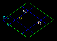
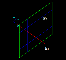
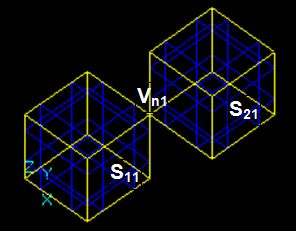
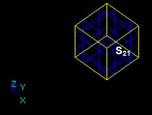
Let us consider edge E1 and face F2:

The result of the GF operation is a compound consisting of 3 shapes:
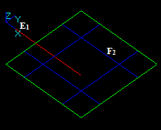
Let us consider edge E1 and face F2:

The result of the GF operation is a compound consisting of 5 shapes:
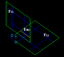
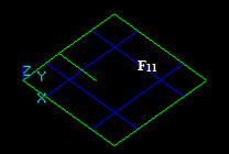
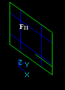
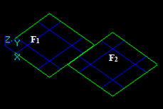
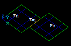
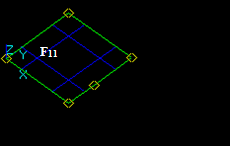
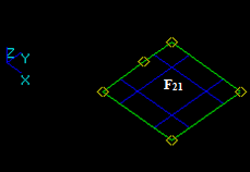
Let us consider edge E1 and shell Sh2 that consists of 2 faces: F21 and F22

The result of the GF operation is a compound consisting of 5 shapes:
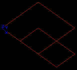
Let us consider wire W1 (E1, E2, E3, E4) and shell Sh2 (F21, F22).

The result of the GF operation is a compound consisting of 2 shapes:
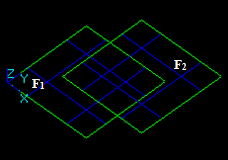
Let us consider 3 faces: F1, F2 and F3.
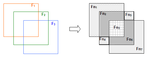
The result of the GF operation is a compound consisting of 7 shapes:
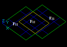
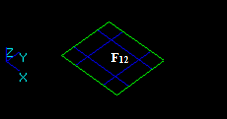
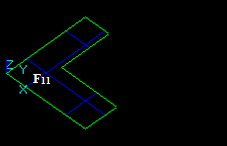
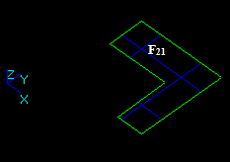
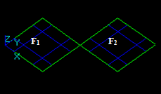
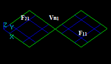
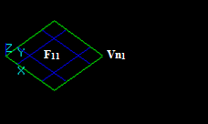
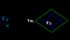
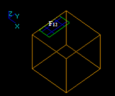
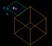
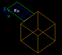
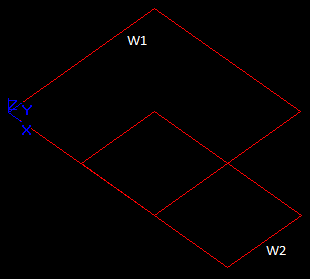
Let us consider shell Sh1 (F11, F12, F13) and face F2.
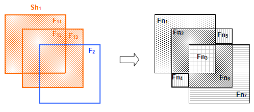
The result of the GF operation is a compound consisting of 4 shapes:
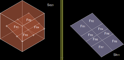
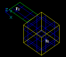
Let us consider shell Sh1 (F11, F12…F16) and solid So2.
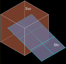
The result of the GF operation is a compound consisting of 2 shapes:
Let us consider compound Cm1 consisting of 2 solids So11 and So12) and solid So2.
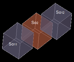
The result of the GF operation is a compound consisting of 4 shapes:
GFA is implemented in the class BOPAlgo_Builder.
The main fields of the class are described in the Table:
| Name | Contents |
|---|---|
| myPaveFiller | Pointer to the BOPAlgo_PaveFiller object |
| myDS | Pointer to the BOPDS_DS object |
| myContext | Pointer to the intersection Context |
| myImages | The Map between the source shape and its images |
| myShapesSD | The Map between the source shape (or split part of source shape) and the shape (or part of shape) that will be used in result due to same domain property. |
The input data for this step is a BOPAlgo_PaveFiller object (in terms of Intersection) at the state after Processing of degenerated edges with the corresponding DS.
| No | Contents | Implementation |
|---|---|---|
| 1 | Check the readiness of the DS and BOPAlgo_PaveFiller. | BOPAlgo_Builder::CheckData() |
| 2 | Build an empty result of type Compound. | BOPAlgo_Builder::Prepare() |
The input data for this step is BOPAlgo_Builder object after Initialisation.
| No | Contents | Implementation |
|---|---|---|
| 1 | Fill myShapesSD by SD vertices using the information from the DS. | BOPAlgo_Builder::FillImagesVertices() |
The input data for this step is BOPAlgo_Builder object after building images for vertices and Type, which is the shape type (TopAbs_VERTEX).
| No | Contents | Implementation |
|---|---|---|
| 1 | For the arguments of type Type. If there is an image for the argument: add the image to the result. If there is no image for the argument: add the argument to the result. | BOPAlgo_Builder::BuildResult() |
The input data for this step is BOPAlgo_Builder object after building result of type vertex.
| No | Contents | Implementation |
|---|---|---|
| 1 | For all pave blocks in the DS. Fill myImages for the original edge E by split edges ESPi from pave blocks. In case of common blocks on edges, use edge ESPSDj that corresponds to the leading pave block and fill myShapesSD by the pairs ESPi/ESPSDj. | BOPAlgo_Builder::FillImagesEdges() |
This step is the same as Building Result of Type Vertex, but for the type Edge.
The input data for this step is:
| No | Contents | Implementation |
|---|---|---|
| 1 | For all arguments of the type Type. Create a container C of the type Type. | BOPAlgo_Builder::FillImagesContainers() |
| 2 | Add to C the images or non-split parts of the Original Shape, taking into account its orientation. | BOPAlgo_Builder::FillImagesContainers() BOPTools_Tools::IsSplitToReverse() |
| 3 | Fill myImages for the Original Shape by the information above. | BOPAlgo_Builder::FillImagesContainers() |
This step is the same as Building Result of Type Vertex but for the type Wire.
The input data for this step is BOPAlgo_Builder object after building result of type Wire.
| No | Contents | Implementation |
|---|---|---|
| 1 | Build Split Faces for all interfered DS shapes Fi of type FACE. | |
| 1.1 | Collect all edges or their images of Fi(ESPij). | BOPAlgo_Builder::BuildSplitFaces() |
| 1.2 | Impart to ESPij the orientation to be coherent with the original one. | BOPAlgo_Builder::BuildSplitFaces() |
| 1.3 | Collect all section edges SEk for Fi. | BOPAlgo_Builder::BuildSplitFaces() |
| 1.4 | Build split faces for Fi (Fi1, Fi2…FiNbSp), where NbSp is the number of split parts (see Building faces from a set of edges for more details). | BOPAlgo_BuilderFace |
| 1.5 | Impart to (Fi1, Fi2…FiNbSp) the orientation coherent with the original face Fi. | BOPAlgo_Builder::BuildSplitFaces() |
| 1.6 | Fill the map mySplits with Fi/(Fi1, Fi2…FiNbSp) | BOPAlgo_Builder::BuildSplitFaces() |
| 2 | Fill Same Domain faces | BOPAlgo_Builder::FillSameDomainFaces |
| 2.1 | Find and collect in the contents of mySplits the pairs of same domain split faces (Fij, Fkl)m, where m is the number of pairs. | BOPAlgo_Builder::FillSameDomainFaces BOPTools_Tools::AreFacesSameDomain() |
| 2.2 | Compute the connexity chains 1) of same domain faces (F1C, F2C… FnC)k, C=0, 1…nCs, where nCs is the number of connexity chains. | BOPAlgo_Builder::FillSameDomainFaces() |
| 2.3 | Fill myShapesSD using the chains (F1C, F2C… FnC)k | BOPAlgo_Builder::FillSameDomainFaces() |
| 2.4 | Add internal vertices to split faces. | BOPAlgo_Builder::FillSameDomainFaces() |
| 2.5 | Fill myImages using myShapesSD and mySplits. | BOPAlgo_Builder::FillSameDomainFaces() |
The example of chains of same domain faces is given in the image:

This step is the same as Building Result of Type Vertex but for the type Face.
The input data for this step is:
The procedure is the same as for building images for wires.
This step is the same as Building Result of Type Vertex but for the type Shell.
The input data for this step is BOPAlgo_Builder object after building result of type Shell.
The following procedure is executed for all interfered DS shapes Si of type SOLID.
| No | Contents | Implementation |
|---|---|---|
| 1 | Collect all images or non-split parts for all faces (FSPij) that have 3D state In Si. | BOPAlgo_Builder::FillIn3DParts () |
| 2 | Collect all images or non-split parts for all faces of Si | BOPAlgo_Builder::BuildSplitSolids() |
| 3 | Build split solids for Si -> (Si1, Si2…SiNbSp), where NbSp is the number of split parts (see Building faces from a set of edges for more details) | BOPAlgo_BuilderSolid |
| 4 | Fill the map Same Domain solids myShapesSD | BOPAlgo_Builder::BuildSplitSolids() |
| 5 | Fill the map myImages | BOPAlgo_Builder::BuildSplitSolids() |
| 6 | Add internal vertices to split solids | BOPAlgo_Builder::FillInternalShapes() |
This step is the same as Building Result of Type Vertex, but for the type Solid.
The input data for this step is:
The procedure is the same as for building images for wires.
This step is the same as Building Result of Type Vertex, but for the type Compsolid.
The input data for this step is as follows:
The procedure is the same as for building images for wires.
This step is the same as Building Result of Type Vertex, but for the type Compound.
The purpose of the step is to correct tolerances of the result to provide its validity in terms of BRepCheck_Analyzer.
The input data for this step is a BOPAlgo_Builder object after building result of type compound.
| No | Contents | Implementation |
|---|---|---|
| 1 | Correct tolerances of vertices on curves | BOPTools_Tools::CorrectPointOnCurve() |
| 2 | Correct tolerances of edges on faces | BOPTools_Tools::CorrectCurveOnSurface() |
| No | Type of Argument | Index of Type | Dimension |
|---|---|---|---|
| 1 | COMPOUND | 0 | One of 0, 1, 2, 3 |
| 2 | COMPSOLID | 1 | 3 |
| 3 | SOLID | 2 | 3 |
| 4 | SHELL | 3 | 2 |
| 5 | FACE | 4 | 2 |
| 6 | WIRE | 5 | 1 |
| 7 | EDGE | 6 | 1 |
| 8 | VERTEX | 7 | 0 |
Let us consider two interfering vertices V1 and V2:


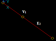
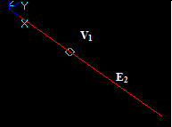
Let us consider vertex V1 and the edge E2, that intersect in a 3D point:
Let us consider vertex V1 and face F2, that intersect in a 3D point:
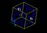
Let us consider vertex V1 and solid S2, that intersect in a 3D point:

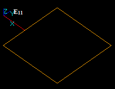
Let us consider edges E1 and E2 that intersect in a 3D point:


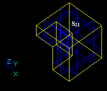
In this case the argument edge E1 has resulting split edges E11 and E12 (image of E1).

In this case the argument edge E2 has resulting split edges E21 and E22 (image of E2).

Let us consider edges E1 and E2 that have a common block:


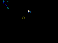
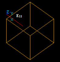
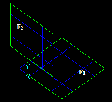
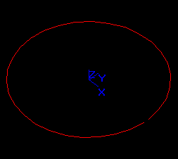
Let us consider edge E1 and face F2 that intersect at a 3D point:
In this case the argument edge E1 has no common parts with the face F2 so the whole image of E1 is in the result.
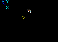
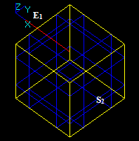
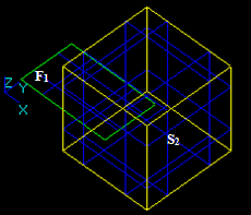
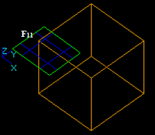
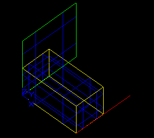
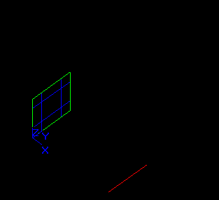
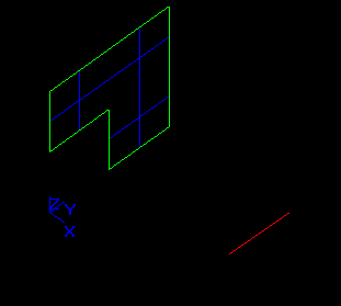
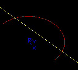
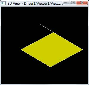
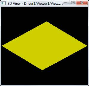
Let us consider edge E1 and face F2 that have a common block:
In this case the argument edge E1 has a common part with face F2 so the corresponding part of the image of E1 is in the result. The yellow square is not a part of the result. It only shows the place of F2.
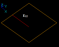
In this case the argument edge E1 has a common part with face F2 so the corresponding part is not included into the result. The yellow square is not a part of the result. It only shows the place of F2.
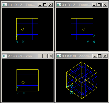
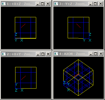
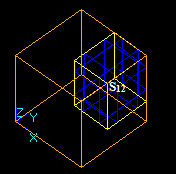
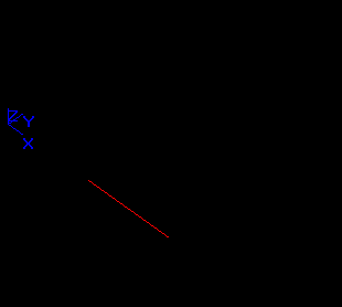
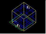
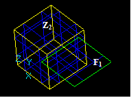
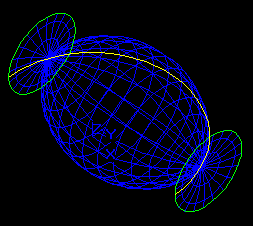
Let us consider edge E1 and solid S2 that intersect at a point:
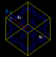
In this case the argument edge E1 has a common part with solid S2 so the corresponding part of the image of E1 is in the result. The yellow square is not a part of the result. It only shows the place of S2.
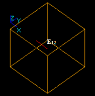
In this case the argument edge E1 has a common part with solid S2 so the corresponding part is not included into the result. The yellow square is not a part of the result. It only shows the place of S2.
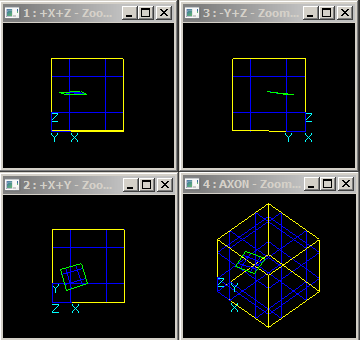
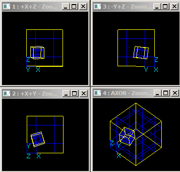
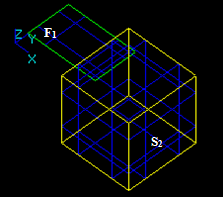
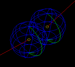
Let us consider edge E1 and solid S2 that have a common block:
In this case the argument edge E1 has a common part with solid S2 so the corresponding part of the image of E1 is in the result. The yellow square is not a part of the result. It only shows the place of S2.
In this case the argument edge E1 has a common part with solid S2 so the corresponding part is not included into the result. The yellow square is not a part of the result. It only shows the place of S2.
Let us consider two intersecting faces F1 and F2:
Let us consider two faces F1 and F2 that have a common part:
Let us consider two faces F1 and F2 that have a common edge:
Let us consider two faces F1 and F2 that have a common vertex:
Let us consider face F1 and solid S2 that have an intersection curve:
Let us consider face F1 and solid S2 that have overlapping faces:
Let us consider face F1 and solid S2 that have overlapping edges:
Let us consider face F1 and solid S2 that have overlapping vertices:
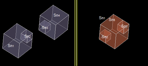
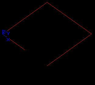
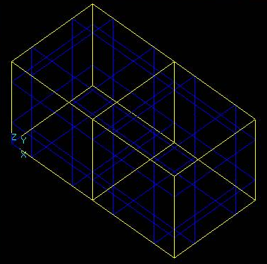
Let us consider two intersecting solids S1 and S2:
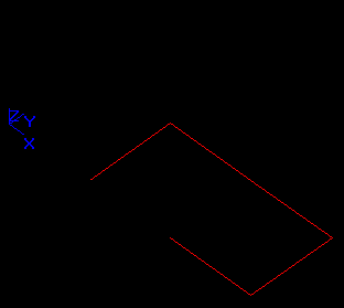
Let us consider two solids S1 and S2 that have a common part on face:
Let us consider two solids S1 and S2 that have overlapping edges:
Let us consider two solids S1 and S2 that have overlapping vertices:

Let us consider Shell Sh and Wire W as the objects and Solid S as the tool:
Let us consider two Wires that have overlapping edges, W1 is the object and W2 is the tool:
BOA is implemented in the class BOPAlgo_BOP. The main fields of this class are described in the Table:
| Name | Contents |
|---|---|
| myOperation | The type of the Boolean operation (Common, Fuse, Cut) |
| myTools | The tools |
| myDims[2] | The values of the dimensions of the arguments |
| myRC | The draft result (shape) |
The main steps of the BOPAlgo_BOP are the same as of BOPAlgo_Builder except for some aspects described in the next paragraphs.
The input data for this step is as follows:
| No | Contents | Implementation |
|---|---|---|
| 1 | For the Boolean operation Fuse add to myRC all images of arguments. | BOPAlgo_BOP::BuildRC() |
| 2 | For the Boolean operation Common or Cut add to myRC all images of argument S1 that are Common for the Common operation and are Not Common for the Cut operation | BOPAlgo_BOP::BuildRC() |
The input data for this step is as follows:
| No | Contents | Implementation |
|---|---|---|
| 1 | For the Type of the Boolean operation Common, Cut with any dimension and operation Fuse with myDim[0] < 3 | |
| 1.1 | Find containers (WIRE, SHELL, COMPSOLID) in the arguments | BOPAlgo_BOP:: BuildShape() |
| 1.2 | Make connexity blocks from splits of each container that are in myRC | BOPTools_Tools::MakeConnexityBlocks() |
| 1.3 | Build the result from shapes made from the connexity blocks | BOPAlgo_BOP:: BuildShape() |
| 1.4 | Add the remaining shapes from myRC to the result | BOPAlgo_BOP:: BuildShape() |
| 2 | For the Type of the Boolean operation Fuse with myDim[0] = 3 | |
| 2.1 | Find internal faces (FWi) in myRC | BOPAlgo_BOP::BuildSolid() |
| 2.2 | Collect all faces of myRC except for internal faces (FWi) -> SFS | BOPAlgo_BOP::BuildSolid () |
| 2.3 | Build solids (SDi) from SFS. | BOPAlgo_BuilderSolid |
| 2.4 | Add the solids (SDi) to the result |
The arguments of BOA are shapes in terms of TopoDS_Shape. The main requirements for the arguments are described in the Algorithms.
Let us consider two interfering vertices: V1 and V2.
The result of Section operation is the compound that contains a new vertex V.
Let us consider vertex V1 and the edge E2, that intersect in a 3D point:
The result of Section operation is the compound that contains vertex V1.
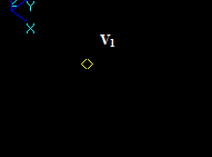
Let us consider vertex V1 and face F2, that intersect in a 3D point:
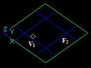
The result of Section operation is the compound that contains vertex V1.
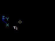
Let us consider vertex V1 and solid Z2. The vertex V1 is inside the solid Z2.
The result of Section operation is an empty compound.
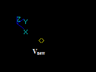
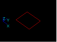
Let us consider edges E1 and E2, that intersect in a 3D point:
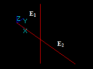
The result of Section operation is the compound that contains a new vertex Vnew.
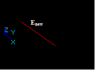
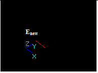
Let us consider edges E1 and E2, that have a common block:
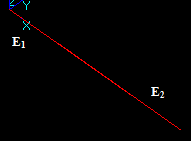
The result of Section operation is the compound that contains a new edge Enew.
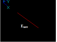
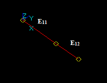
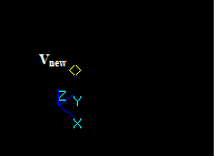
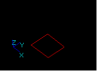
Let us consider edge E1 and face F2, that intersect at a 3D point:
The result of Section operation is the compound that contains a new vertex Vnew.
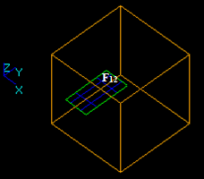
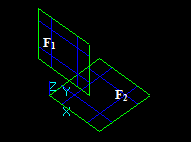
Let us consider edge E1 and face F2, that have a common block:
The result of Section operation is the compound that contains new edge Enew.
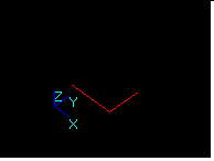
Let us consider edge E1 and solid Z2, that intersect at a point:
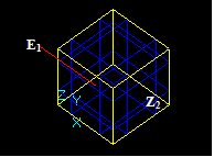
The result of Section operation is the compound that contains a new vertex Vnew.
Let us consider edge E1 and solid Z2, that have a common block at a face:
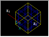
The result of Section operation is the compound that contains a new edge Enew.

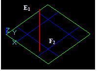
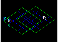
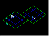
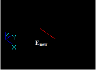
Let us consider two intersecting faces F1 and F2:
The result of Section operation is the compound that contains a new edge Enew.
Let us consider two faces F1 and F2 that have a common part:
The result of Section operation is the compound that contains 4 new edges.
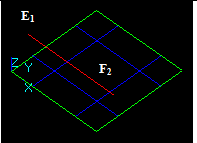
Let us consider two faces F1 and F2 that have a overlapping edges:
The result of Section operation is the compound that contains a new edge Enew.
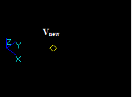
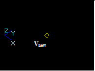
Let us consider two faces F1 and F2 that have overlapping vertices:
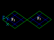
The result of Section operation is the compound that contains a new vertex Vnew.
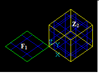
Let us consider face F1 and solid Z2 that have an intersection curve:
The result of Section operation is the compound that contains new edges.
Let us consider face F1 and solid Z2 that have overlapping faces:
The result of Section operation is the compound that contains new edges
Let us consider face F1 and solid Z2 that have a common part on edge:
The result of Section operation is the compound that contains a new edge Enew.
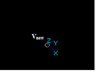
Let us consider face F1 and solid Z2 that have overlapping vertices:
The result of Section operation is the compound that contains a new vertex Vnew.
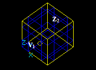
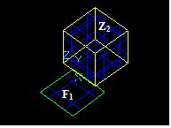
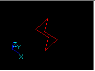
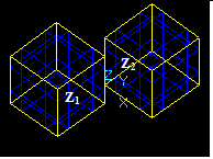
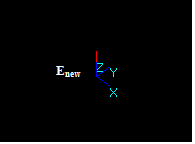
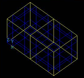
Let us consider two intersecting solids Z1 and Z2:
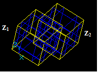
The result of Section operation is the compound that contains new edges.
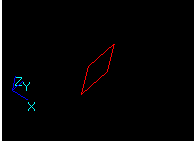
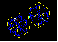
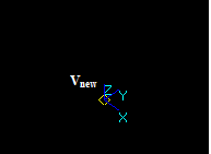
Let us consider two solids Z1 and Z2 that have a common part on face:
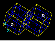
The result of Section operation is the compound that contains new edges.
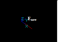
Let us consider two solids Z1 and Z2 that have overlapping edges:
The result of Section operation is the compound that contains a new edge Enew.
Let us consider two solids Z1 and Z2 that have overlapping vertices:
The result of Section operation is the compound that contains a new vertex Vnew.
SA is implemented in the class BOPAlgo_Section. The class has no specific fields. The main steps of the BOPAlgo_Section are the same as of BOPAlgo_Builder except for the following steps:
| No | Contents | Implementation |
|---|---|---|
| 1 | Build the result of the operation using all information contained in FaceInfo, Common Block, Shared entities of the arguments, etc. | BOPAlgo_Section:: BuildSection() |
The chapter describes the problems that are considered as Algorithm limitations. In most cases an Algorithm failure is caused by a combination of various factors, such as self-interfered arguments, inappropriate or ungrounded values of the argument tolerances, adverse mutual position of the arguments, tangency, etc.
A lot of failures of GFA algorithm can be caused by bugs in low-level algorithms: Intersection Algorithm, Projection Algorithm, Approximation Algorithm, Classification Algorithm, etc.
The description below illustrates some known GFA limitations. It does not enumerate exhaustively all problems that can arise in practice. Please, address cases of Algorithm failure to the OCCT Maintenance Service.
Each argument should be valid (in terms of BRepCheck_Analyzer), or conversely, if the argument is considered as non-valid (in terms of BRepCheck_Analyzer), it cannot be used as an argument of the algorithm.
The class BRepCheck_Analyzer is used to check the overall validity of a shape. In OCCT a Shape (or its sub-shapes) is considered valid if it meets certain criteria. If the shape is found as invalid, it can be fixed by tools from ShapeAnalysis, ShapeUpgrade and ShapeFix packages.
However, it is important to note that class BRepCheck_Analyzer is just a tool that can have its own problems; this means that due to a specific factor(s) this tool can sometimes provide a wrong result.
Let us consider the following example:
The Analyzer checks distances between couples of 3D check-points (Pi, PSi) of edge E on face F. Point Pi is obtained from the 3D curve (at the parameter ti) of the edge. PSi is obtained from 2D curve (at the parameter ti) of the edge on surface S of face F. To be valid the distance should be less than Tol(E) for all couples of check-points. The number of these check-points is a predefined value (e.g. 23).
Let us consider the case when edge E is recognized valid (in terms of BRepCheck_Analyzer).
Further, after some operation, edge E is split into two edges E1 and E2. Each split edge has the same 3D curve and 2D curve as the original edge E.
Let us check E1 (or E2). The Analyzer again checks the distances between the couples of check-points points (Pi, PSi). The number of these check-points is the same constant value (23), but there is no guarantee that the distances will be less than Tol(E), because the points chosen for E1 are not the same as for E.
Thus, if E1 is recognized by the Analyzer as non-valid, edge E should also be non-valid. However E has been recognized as valid. Thus the Analyzer gives a wrong result for E.
The fact that the argument is a valid shape (in terms of BRepCheck_Analyzer) is a necessary but insufficient requirement to produce a valid result of the Algorithms.
The argument should not be self-interfered, i.e. all sub-shapes of the argument that have geometrical coincidence through any topological entities (vertices, edges, faces) should share these entities.
The compound of two edges E1 and E2 is a self-interfered shape and cannot be used as the argument of the Algorithms.

The edge E is a self-interfered shape and cannot be used as an argument of the Algorithms.

The face F is a self-interfered shape and cannot be used as an argument of the Algorithms.

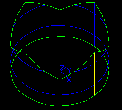
The face F has been obtained by revolution of edge E around line L.
In spite of the fact that face F is valid (in terms of BRepCheck_Analyzer) it is a self-interfered shape and cannot be used as the argument of the Algorithms.
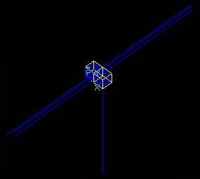
Let us consider edge E based on a non-closed circle.
The distance between the vertices of E is D=0.69799. The values of the tolerances Tol(V1)=Tol(V2)=0.5.
In spite of the fact that the edge E is valid in terms of BRepCheck_Analyzer, it is a self-interfered shape because its vertices are interfered. Thus, edge E cannot be used as an argument of the Algorithms.
Let us consider solid S containing vertex V.
The value of tolerance Tol(V)= 50.000075982061.
In spite of the fact that solid S is valid in terms of BRepCheck_Analyzer it is a self-interfered shape because vertex V is interfered with a lot of sub-shapes from S without any topological connection with them. Thus solid S cannot be used as an argument of the Algorithms.
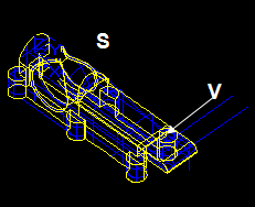
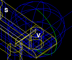
The parameterization of some surfaces (cylinder, cone, surface of revolution) can be the cause of limitation.
The parameterization range for cylindrical surface is:
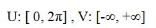
The range of U coordinate is always restricted while the range of V coordinate is non-restricted.
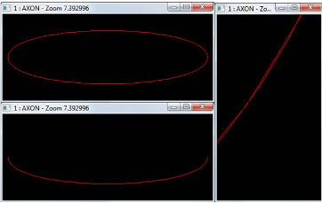
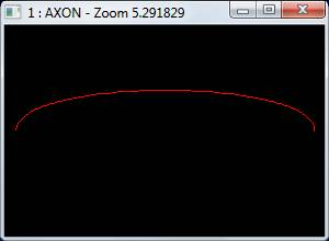
Let us consider a cylinder-based Face 1 with radii R=3 and H=6.
Let us also consider a cylinder-based Face 2 with radii R=3000 and H=6000 (resulting from scaling Face 1 with scale factor ScF=1000).
Please, pay attention to the Zoom value of the Figures.
It is obvious that starting with some value of ScF, e.g. ScF>1000000, all sloped p-Curves on Face 2 will be almost vertical. At least, there will be no difference between the values of angles computed by standard C Run-Time Library functions, such as double acos(double x). The loss of accuracy in computation of angles can cause failure of some BP sub-algorithms, such as building faces from a set of edges or building solids from a set of faces.
It is possible to create shapes that use sub-shapes of lower order to avoid gaps in the tolerance-based data model.
Let us consider the following example:
The values of tolerances Tol(V1) and Tol(V2) are big enough to fix the gaps between the ends of the edges, but the vertices V1 and V2 do not contain any information about the trajectories connecting the corresponding ends of the edges. Thus, the trajectories are undefined. This will cause failure of some sub-algorithms of BP. For example, the sub-algorithms for building faces from a set of edges use the information about all edges connected in a vertex. The situation when a vertex has several pairs of edges such as above will not be solved in a right way.
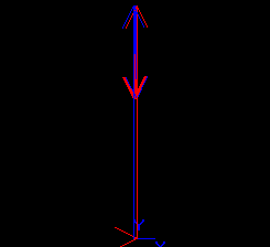
Let us consider the intersection between two edges:
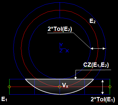
The result of pure intersection between E1 and E2 is vertex Vx {0,-10,0}.
The result of intersection taking into account tolerances is the common zone CZ (part of 3D-space where the distance between the curves is less than or equals to the sum of edge tolerances.
The Intersection Part of Algorithms uses the result of pure intersection Vx instead of CZ for the following reasons:
The following limitations result from modeling errors or inaccuracies.
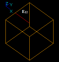
Let us consider two planar rectangular faces F1 and F2.
The intersection curve between the planes is curve C12. The curve produces a new intersection edge EC12. The edge goes through vertices V1 and V2 thanks to big tolerance values of vertices Tol(V1) and Tol(V2). So, two straight edges E12 and EC12 go through two vertices, which is impossible in this case.

The problem cannot be solved in general, because the length of E12 can be infinite and the values of Tol(V1) and Tol(V2) theoretically can be infinite too.
In a particular case the problem can be solved in several ways:
It is easy to see that if C12 is slightly above the tolerance spheres of V1 and V2 the problem does not appear.
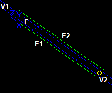
Let us consider two edges E1 and E2, which have common vertices V1 and V2. The edges E1 and E2 have 3D-curves C1 and C2. Tol(E1)=1.e-7, Tol(E2)=1.e-7.
C1 practically coincides in 3D with C2. The value of deflection is Dmax (e.g. Dmax=1.e-6).

The evident and prospective result should be the Common Block between E1 and E2. However, the result of intersection differs.

The result contains three new vertices Vx1, Vx2 and Vx3, 8 new edges (V1, Vx1, Vx2, Vx3, V2) and no Common Blocks. This is correct due to the source data: Tol(E1)=1.e-7, Tol(E2)=1.e-7 and Dmax=1.e-6.
In this particular case the problem can be solved by several ways:
The example can be extended from 1D (edges) to 2D (faces).

The comments and recommendations are the same as for 1D case above.
Let us consider vertex V1 and edge E2.

Vertex V1 interferes with vertices V12 and V22. So vertex V21 should interfere with vertex V22, which is impossible because vertices V21 and V22 are the vertices of edge E2, thus V21 is not equal to V22.
The problem cannot be solved in general, because the length can be as small as possible to provide validity of E2 (in the extreme case: Length (E2) = Tol(V21) + Tol(V22) + e, where e-> 0).
In a particular case the problem can be solved by refinement of arguments, i.e. by decreasing the values of Tol(V21), Tol(V22) and Tol(V1).
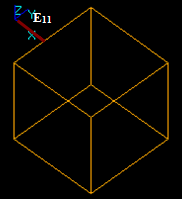
Let us consider vertex V2 and wire consisting of edges E11 and E12.

The arguments themselves are not self-intersected. Vertex V2 interferes with edges E11 and E12. Thus, edge E11 should interfere with edge E22, but it is impossible because edges E11 and E12 cannot interfere by the condition.
The cases when a non-self-interfered argument (or its sub-shapes) become interfered due to the intersections with other arguments (or their sub-shapes) are considered as limitations for the Algorithms.
The previous chapters describe so called Basic Operations. Most of tasks can be solved using Basic Operations. Nonetheless, there are cases that can not be solved straightforwardly by Basic Operations. The tasks are considered as limitations of Basic Operations.
The chapter is devoted to Advanced Options. In some cases the usage of Advanced Options allows overcoming the limitations, improving the quality of the result of operations, robustness and performance of the operators themselves.
Fuzzy Boolean operation is the option of Basic Operations (GFA, BOA, PA and SA), in which additional user-specified tolerance is used. This option allows operators to handle robustly cases of touching and near-coincident, misalignment entities of the arguments.
The Fuzzy option is useful on the shapes with gaps or embeddings between the entities of these shapes which are not covered by the tolerance values of these entities. Such shapes can be the result of modeling mistakes, or translating process, or import from other systems with loss of precision, or errors in some algorithms.
Most likely, the Basic Operations will give unsatisfactory results on such models. The result may contain unexpected and unwanted small entities, faulty entities (in terms of BRepCheck_Analyzer), or there can be no result at all.
With the Fuzzy option it is possible to get the expected result – it is just necessary to define the appropriate value of fuzzy tolerance for the operation. To define that value it is necessary to measure the value of the gap (or the value of embedding depth) between the entities of the models, slightly increase it (to make the shifted entities coincident in terms of their tolerance plus the additional one) and pass it to the algorithm.
Fuzzy option is included in interface of Intersection Part (class BOPAlgo_PaveFiller) and application programming interface (class BRepAlgoAPI_BooleanOperation)
The following examples demonstrate the advantages of usage Fuzzy option operations over the Basic Operations in typical situations.
In this example the cylinder (shown in yellow and transparent) is subtracted from the box (shown in red). The cylinder is shifted by 5e-5 relatively to the box along its axis (the distance between rear faces of the box and cylinder is 5e-5).
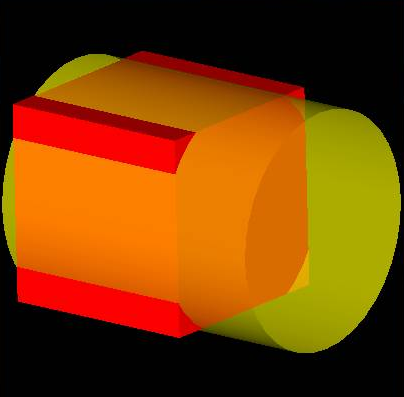
The following results are obtained using Basic Operations and the Fuzzy ones with the fuzzy value 5e-5:
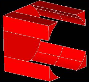
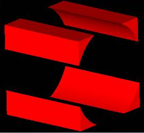
In this example Fuzzy option allows eliminating a very thin part of the result shape produced by Basic algorithm due to misalignment of rear faces of the box and the cylinder.
In this example two boxes are fused. One of them has dimensions 10*10*10, and the other is 10*10.000001*10.000001 and adjacent to the first one. There is no gap in this case as the surfaces of the neighboring faces coincide, but one box is slightly greater than the other.
The following results are obtained using Basic Operations and the Fuzzy ones with the fuzzy value 1e-6:
In this example Fuzzy option allows eliminating an extremely narrow face in the result produced by Basic operation.
In this example the small planar face (shown in orange) is subtracted from the big one (shown in yellow). There is a gap 1e-5 between the edges of these faces.
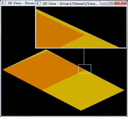
The following results are obtained using Basic Operations and the Fuzzy ones with the fuzzy value 1e-5:
In this example Fuzzy options eliminated a pin-like protrusion resulting from the gap between edges of the argument faces.
In this example the small edge is subtracted from the big one. The edges are overlapping not precisely, with max deviation between them equal to 5.28004e-5. We will use 6e-5 value for Fuzzy option.
The following results are obtained using Basic Operations and the Fuzzy ones with the fuzzy value 6e-5:
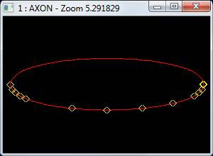
This example stresses not only the validity, but also the performance issue. The usage of Fuzzy option with the appropriate value allows processing the case much faster than with the pure Basic operation. The performance gain for the case is 45 (Processor: Intel(R) Core(TM) i5-3450 CPU @ 3.10 GHz).
The chapter contains some examples of the OCCT Boolean Component usage. The usage is possible on two levels: C++ and Tcl.
The package BRepAlgoAPI provides the Application Programming Interface of the Boolean Component.
The package consists of the following classes:

The detailed description of the classes can be found in the corresponding .hxx files. The examples are below in this chapter.
The package BOPTest provides the usage of the Boolean Component on Tcl level. The method BOPTest::APICommands contains corresponding Tcl commands:
The examples of how to use the commands are below in this chapter.
The following example illustrates how to use General Fuse operator:
The following example illustrates how to use Common operation:
The following example illustrates how to use Fuse operation:
The following example illustrates how to use Cut operation:
The following example illustrates how to use Section operation:
 1.8.10