

Tue, 03/31/2015 - 22:11
Hello,
I'm having trouble extracting the boundary representation for a projected shape. For some reason, the projected shape's edges are much lower resolution than that used for display by AIS.
I use Prs3d_Projector to project the loaded model.
I use TopExp_Explorer (with TopAbs_EDGE) to query for the edges of the projected shape. Also, using TopExp_Explorer (with TopAbs_FACE) returns no faces.
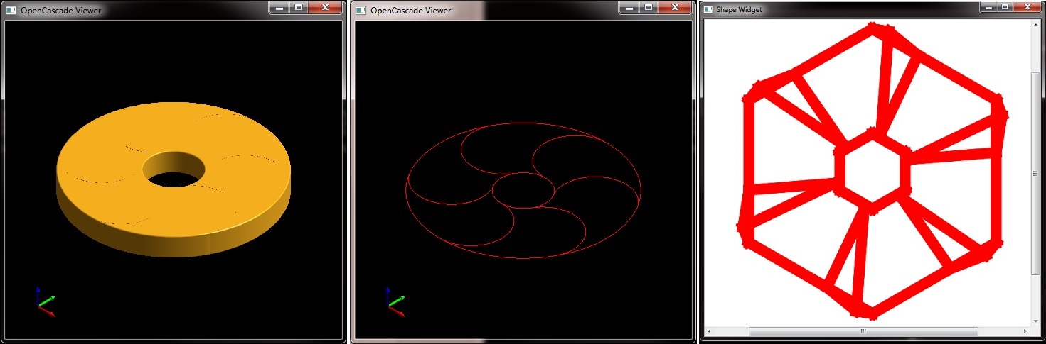
Below is an image of the CAD file as opened by an OpenCascade application. It is then projected onto the X/Y plane to extract the boundary representation. This projected shape is explored to retrieve the edges (which are incorrect).
QUESTION 1: Is there a way to get a polygonal representation (e.g. sets of vertices) of the projected shape?
QUESTION: Why is the wireframe of the projected shape lower resolution?
Thanks,
Ben
Wed, 04/01/2015 - 00:39
I was able to Google and find out how to get the curve information for TopoDS_Edge. It wasn't clear in any of the OpenCascade documentation for TopoDS_Edge that I'd come across thus far. In a nutshell, the image I posted only contained vertices for the edges at the endpoints.
Wed, 04/01/2015 - 23:34
I was able to discretize the pojected shape's edges. However, the edges appear to be boundary regions rather than the actual shape.
Any help is greatly appreciated!
Btw, my apologies for not using code tags below, I didn't see how to do that.
Here's where I project my shape ...
Prs3d_Projector myProj(false, 0,
projVect.x, projVect.y, projVect.z,
eyeVect.x, eyeVect.y, eyeVect.z,
upVect.x, upVect.y, upVect.z);
myAlgo->Projector(myProj.Projector());
myAlgo->Update();
HLRBRep_HLRToShape aHLRToShape(myAlgo);
mShapeProj = aHLRToShape.VCompound();
Here's where I "try" to discretize the edges of the shape ...
cout << "Edges of projected shape:\n";
TopExp_Explorer edgeExpl;
int ii;
for(ii=0, edgeExpl.Init(mShapeProj, TopAbs_EDGE); edgeExpl.More(); ++ii, edgeExpl.Next())
{
TopoDS_Edge edge = TopoDS::Edge(edgeExpl.Current());
cout << ii << "t=" << edge.ShapeType() << " isCurve=" << BRep_Tool::IsGeometric(edge) << " ";
Handle_Geom2d_Curve curve2D;
Handle_Geom_Surface surface;
TopLoc_Location location;
Standard_Real first, last;
BRep_Tool::CurveOnSurface(edge, curve2D, surface, location, first, last);
gp_Pnt pnt = gp_Pnt(0.0,0.0,0.0).Transformed(location);
gp_Pln plane(0.0, 0.0, 1.0, 0.0);
Handle_Geom_Curve curve3D = GeomAPI::To3d(curve2D, plane);
if(!curve3D.IsNull())
{
GeomAdaptor_Curve curveAdaptator(curve3D);
GCPnts_UniformDeflection discretizer;
double deflection(0.1);
discretizer.Initialize(curveAdaptator, deflection);
// Did the algorithm converge?
if(discretizer.IsDone())
{
cout << ii << "#points=" << discretizer.NbPoints() << " ";
for(int jj=0; jj
Thu, 04/02/2015 - 18:53
This solution is now just for someone else since I figured it out. I had forgotten to include the first and last parameters for the descretizer. Looking at the image you'll see that the curves look like expected.
discretizer.Initialize(curveAdaptator, deflection, first, last);