

Wed, 02/01/2023 - 16:23
Forums:
Hello,
I have defined a scene and use it to render images using path tracing with OCCT770.
The components of the scene are:
- a CAD modell (stud)
- light source (V3d_PositionalLight)
- a grid that is placed in front of the light source (stripes)
- a camera
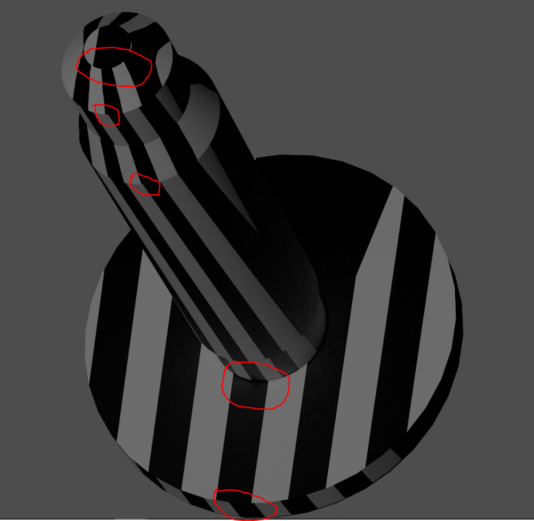
The generated stripes do not seem to be right and obviously depend on the angle between the light and the face normal (see attached image).
It looks to me like OCCT bug. Can anyone confirm that?
Or maybe there is something I'm doing wrong defining the scene?
Thanks
Pawel
Attachments:
Wed, 02/01/2023 - 17:20
Is it an orthographic protection? How it looks with perspective camera?
Mon, 02/06/2023 - 14:27
This is a perspective view. But it doesn't matter if the viewer is in orthographic or perspective mode. The effect is the same.
Image (orthographic projection) attached.
Tue, 02/07/2023 - 12:45
Would be nice if you could share a Draw Harness script or C++ code with the model for reproducing this scenario to give some comments why this might happen.
Tue, 02/07/2023 - 18:19
OK, I'll try to create a corresponding Draw Harness script and will upload it here.
Tue, 02/07/2023 - 19:20
Ok, I have written the following script (see below). I'm not sure if it reproduces my effect in 100%. But it can be clearly seen that at the border of the cylindrical face and the plane the light does not traverse correctly.
I will try to create some more examples tomorrow.
pload ALL
vinit
pcylinder c1 25 50
vdisplay c1
vsetdispmode c1 1
vsetmaterial c1 plastic
vsetcolor c1 white
box b1 50 5 -200 1 50 400
vdisplay b1
vsetdispmode b1 1
box b2 50 -5 -200 1 -50 400
vdisplay b2
vsetdispmode b2 1
vfit
vraytrace 1
vrenderparams -shadows 1 -reflections 1 -fsaa 1
vlight redlight -type POSITIONAL -headlight 0 -pos 100 0 100 -color RED -intensity 10
Wed, 02/08/2023 - 14:15
I was able to create a script that shows the problem.
Image attached.
pload ALL
vinit
pcylinder c0 50 5
vdisplay c0
vsetdispmode c0 1
vsetmaterial c0 plastic
vsetcolor c0 white
pcylinder c1 25 50
vdisplay c1
vsetdispmode c1 1
vsetmaterial c1 plastic
vsetcolor c1 white
box b1 1000 -0.5 -200 1 1 400
vdisplay b1
vsetdispmode b1 1
box b2 1000 -1.5 -200 1 -1 400
vdisplay b2
vsetdispmode b2 1
box b3 1000 1.5 -200 1 1 400
vdisplay b3
vsetdispmode b3 1
vfit
vraytrace 1
vrenderparams -shadows 1 -reflections 1 -fsaa 1
vlight redlight -type POSITIONAL -headlight 0 -pos 1025 0 200 -color RED -intensity 10
Wed, 02/08/2023 - 15:02
just one more thing: I ran all the scripts with OCCT 770 but the effect should be the same in lower versions also.
Wed, 02/08/2023 - 17:21
Looks like accumulated error of single precision floating point math. As larger distance of the light - the harder effect.
Thu, 02/09/2023 - 12:09
Would there be a work-around for this problem?